

Biomechanics and strain mapping in bone as related to immediately-loaded dental implants
- PMID: 26162549
- PMCID: PMC4663100
- DOI: 10.1016/j.jbiomech.2015.05.014
Biomechanics and strain mapping in bone as related to immediately-loaded dental implants
Abstract
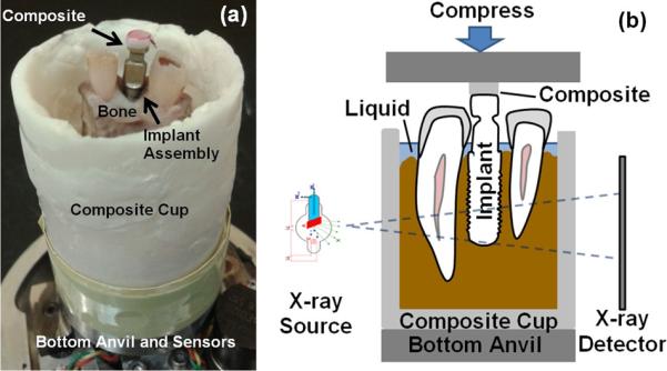
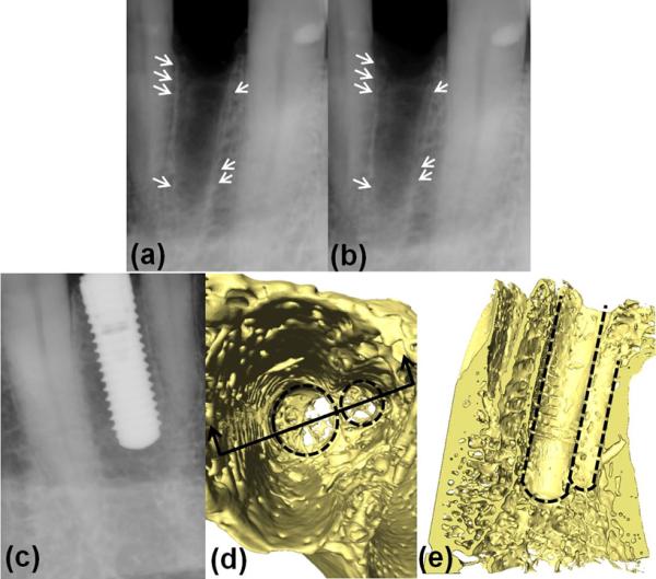
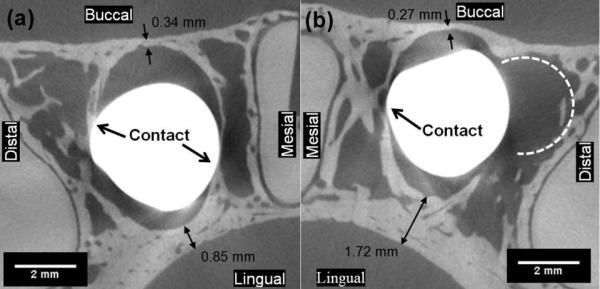
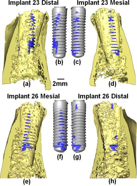
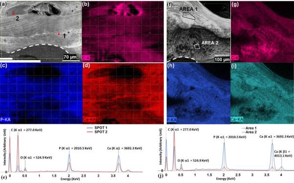
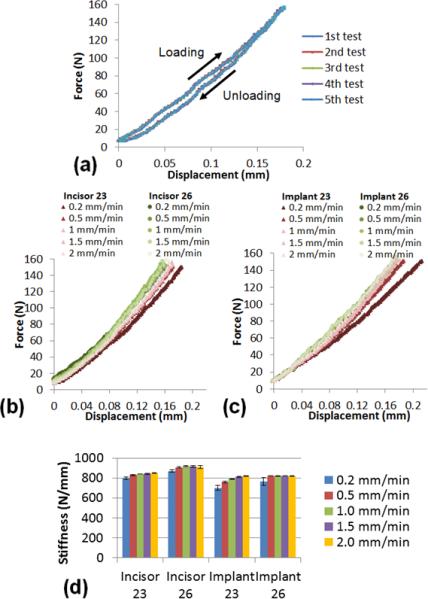
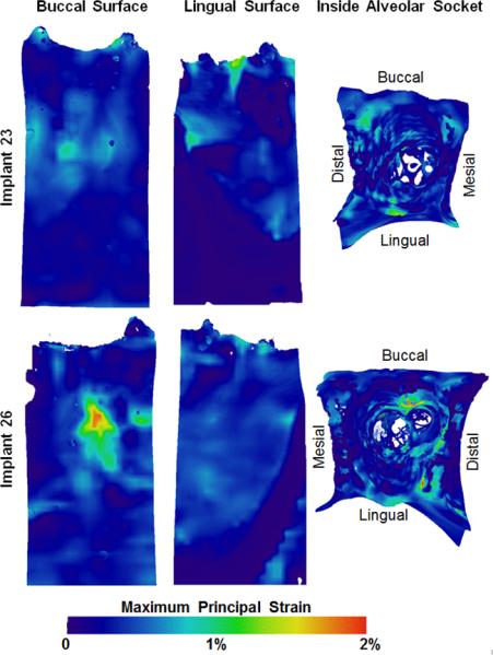
The effects of alveolar bone socket geometry and bone-implant contact on implant biomechanics, and resulting strain distributions in bone were investigated. Following extraction of lateral incisors on a cadaver mandible, implants were placed immediately and bone-implant contact area, stability implant biomechanics and bone strain were measured. In situ biomechanical testing coupled with micro X-ray microscopy (µ-XRM) illustrated less stiff bone-implant complexes (701-822 N/mm) compared with bone-periodontal ligament (PDL)-tooth complexes (791-913 N/mm). X-ray tomograms illustrated that the cause of reduced stiffness was due to limited bone-implant contact. Heterogeneous elemental composition of bone was identified by using energy dispersive X-ray spectroscopy (EDS). The novel aspect of this study was the application of a new experimental mechanics method, that is, digital volume correlation, which allowed mapping of strains in volumes of alveolar bone in contact with a loaded implant. The identified surface and subsurface strain concentrations were a manifestation of load transferred to bone through bone-implant contact based on bone-implant geometry, quality of bone, implant placement, and implant design. 3D strain mapping indicated that strain concentrations are not exclusive to the bone-implant contact regions, but also extend into bone not directly in contact with the implant. The implications of the observed strain concentrations are discussed in the context of mechanobiology. Although a plausible explanation of surgical complications for immediate implant treatment is provided, extrapolation of results is only warranted by future systematic studies on more cadaver specimens and/or in vivo models.
Keywords: Alveolar bone; Bone–implant contact; Digital volume correlation; Implant; Strain.
Copyright © 2015 Elsevier Ltd. All rights reserved.
Figures
Similar articles
-
Evaluation of optimal taper of immediately loaded wide-diameter implants: a finite element analysis.J Oral Implantol. 2013 Apr;39(2):123-32. doi: 10.1563/AAID-JOI-D-11-00104. Epub 2011 Sep 9. J Oral Implantol. 2013. PMID: 21905902
-
Influence of implant design on the biomechanical environment of immediately placed implants: computed tomography-based nonlinear three-dimensional finite element analysis.Int J Oral Maxillofac Implants. 2011 Nov-Dec;26(6):1279-87. Int J Oral Maxillofac Implants. 2011. PMID: 22167434
-
Bone loss around immediately loaded transitional implants: histologic and microcomputed tomographic analysis--a case report.Int J Periodontics Restorative Dent. 2012 Dec;32(6):e195-203. Int J Periodontics Restorative Dent. 2012. PMID: 23057063
-
Immediate loading in partially and completely edentulous jaws: a review of the literature with clinical guidelines.Periodontol 2000. 2014 Oct;66(1):153-87. doi: 10.1111/prd.12040. Periodontol 2000. 2014. PMID: 25123767 Review.
-
A Review: Non-Contact and Full-Field Strain Mapping Methods for Experimental Mechanics and Structural Health Monitoring.Sensors (Basel). 2024 Oct 12;24(20):6573. doi: 10.3390/s24206573. Sensors (Basel). 2024. PMID: 39460052 Free PMC article. Review.
Cited by
-
Effects of implant buccal distance on peri-implant strain: A Micro-CT based finite element analysis.J Mech Behav Biomed Mater. 2021 Apr;116:104325. doi: 10.1016/j.jmbbm.2021.104325. Epub 2021 Jan 13. J Mech Behav Biomed Mater. 2021. PMID: 33485035 Free PMC article.
-
3D full-field strain in bone-implant and bone-tooth constructs and their morphological influential factors.J Mech Behav Biomed Mater. 2020 Oct;110:103858. doi: 10.1016/j.jmbbm.2020.103858. Epub 2020 May 19. J Mech Behav Biomed Mater. 2020. PMID: 32501222 Free PMC article.
-
Voxel-based micro-finite element analysis of dental implants in a human cadaveric mandible: Tissue modulus assignment and sensitivity analyses.J Mech Behav Biomed Mater. 2019 Jun;94:229-237. doi: 10.1016/j.jmbbm.2019.03.008. Epub 2019 Mar 13. J Mech Behav Biomed Mater. 2019. PMID: 30925312 Free PMC article.
-
Bone Damage Evolution Around Integrated Metal Screws Using X-Ray Tomography - in situ Pullout and Digital Volume Correlation.Front Bioeng Biotechnol. 2020 Aug 5;8:934. doi: 10.3389/fbioe.2020.00934. eCollection 2020. Front Bioeng Biotechnol. 2020. PMID: 32850760 Free PMC article.
-
Investigating the Mechanical Characteristics of Bone-Metal Implant Interface Using in situ Synchrotron Tomographic Imaging.Front Bioeng Biotechnol. 2019 Jan 21;6:208. doi: 10.3389/fbioe.2018.00208. eCollection 2018. Front Bioeng Biotechnol. 2019. PMID: 30719433 Free PMC article.
References
-
- Akça K, Akkocaoglu M, Cömert A, Tekdemir I, Cehreli MC. Bone strains around immediately loaded implants supporting mandibular overdentures in human cadavers. Int. J. Oral Maxillofac. Implants. 2007;22:101–9. - PubMed
-
- Akça K, Chang T, Tekdemir I, Fanuscu MI. Biomechanical aspects of initial intraosseous stability and implant design: a quantitative micro-morphometric analysis. Clin. Oral Implants Res. 2006;17:465–72. - PubMed
-
- Akkocaoglu M, Uysal S, Tekdemir I, Akca K, Cehreli MC. Implant design and intraosseous stability of immediately placed implants: a human cadaver study. Clin. Oral Implants Res. 2005;16:202–9. - PubMed
-
- Alsaadi G, Quirynen M, Michiels K, Jacobs R, van Steenberghe D. A biomechanical assessment of the relation between the oral implant stability at insertion and subjective bone quality assessment. J. Clin. Periodontol. 2007;34:359–66. - PubMed
-
- Asundi A, Kishen A. A strain gauge and photoelastic analysis of in vivo strain and in vitro stress distribution in human dental supporting structures. Arch. Oral Biol. 2000a;45:543–50. - PubMed
Publication types
MeSH terms
Substances
Grants and funding
LinkOut - more resources
Full Text Sources
Other Literature Sources
