. 2011 Aug;39B(3):149-158.
doi: 10.1002/cmr.b.20202.

Semipermeable Hollow Fiber Phantoms for Development and Validation of Perfusion-Sensitive MR Methods and Signal Models

Affiliations

Semipermeable Hollow Fiber Phantoms for Development and Validation of Perfusion-Sensitive MR Methods and Signal Models

J R Anderson et al. Concepts Magn Reson Part B Magn Reson Eng. 2011 Aug.

Abstract

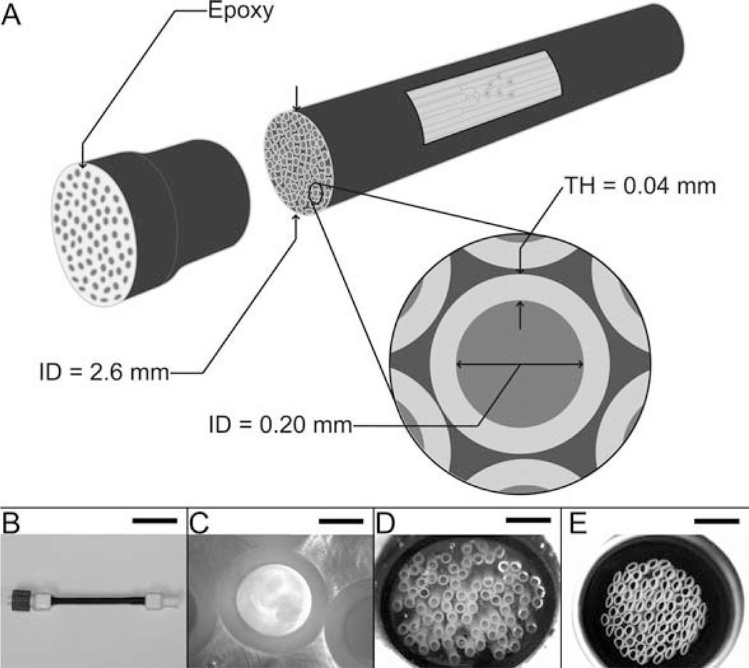
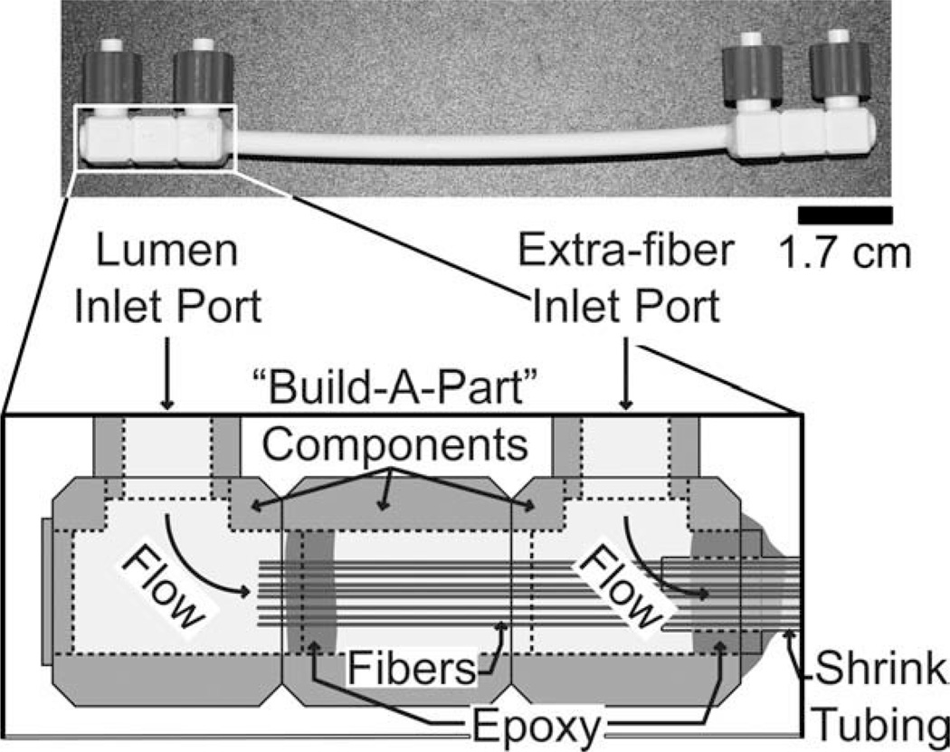
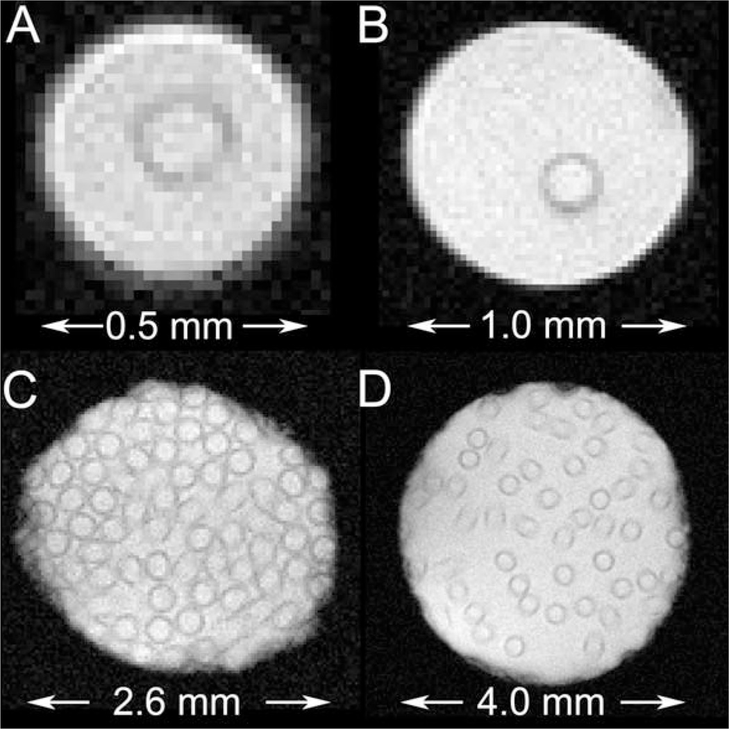
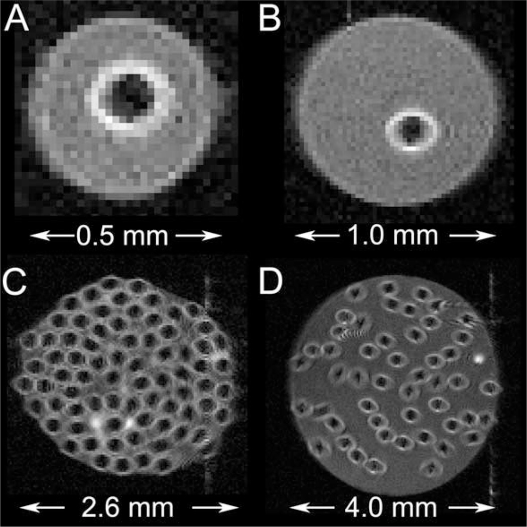
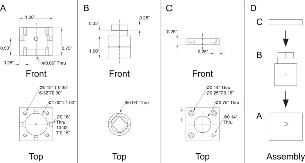
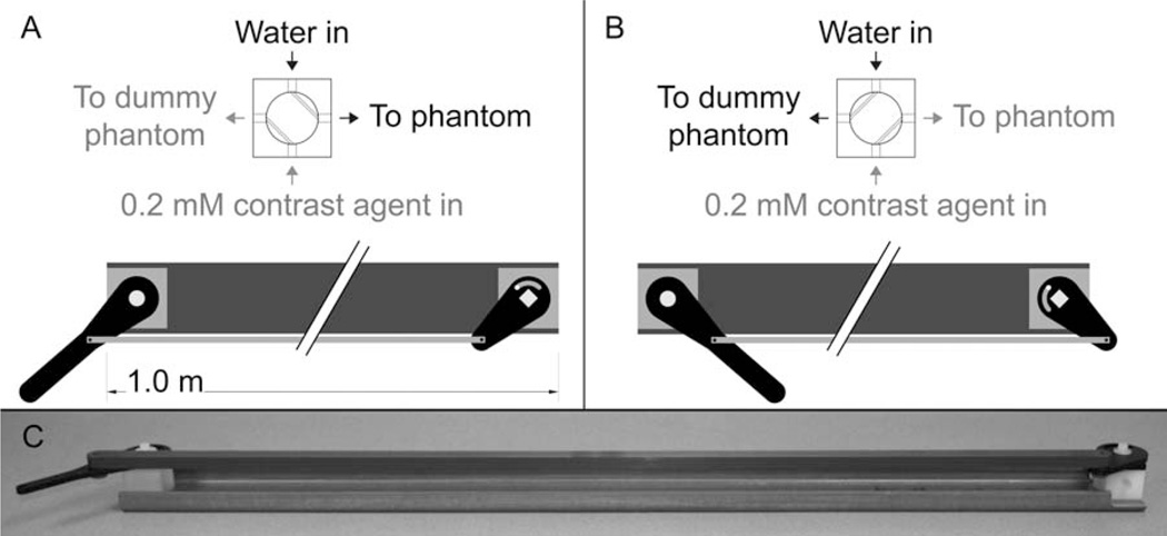
Two semipermeable, hollow fiber phantoms for the validation of perfusion-sensitive magnetic resonance methods and signal models are described. Semipermeable hollow fibers harvested from a standard commercial hemodialysis cartridge serve to mimic tissue capillary function. Flow of aqueous media through the fiber lumen is achieved with a laboratory-grade peristaltic pump. Diffusion of water and solute species (e.g., Gd-based contrast agent) occurs across the fiber wall, allowing exchange between the lumen and the extralumenal space. Phantom design attributes include: i) small physical size, ii) easy and low-cost construction, iii) definable compartment volumes, and iv) experimental control over media content and flow rate.

Keywords: MR phantom design; dialyzer; hollow fiber bioreactor; perfusion; semipermeable hollow fiber.


Figures

Figure 1
Figure 1
Single-fiber phantom. Left inset: schematic of the interior of the Luer-lock end piece. Center inset: schematic interior of the center portion of the phantom; sagittal view. Right inset: schematic interior of the center portion of the phantom; transaxial view.
Figure 2
Figure 2
Multifiber phantom; lumenal compartment access only. A: Schematic of the design and dimensions of the multifiber phantom. B: Photograph of the multifiber phantom (scale bar = 2.50 cm). C: Microscope image of a transaxial cross-section of a single fiber (40× magnification, scale bar = 100 µm). D: Microscope image of a transaxial cross-section of the end of the phantom, i.e., fibers fixed in epoxy (4× magnification, scale bar = 1 mm). E: Microscope image of a transaxial cross-section of the center portion of the phantom; fibers tightly bundled (4×, scale bar = 1 mm). Note: the slight deformity seen in some fibers in E occurred while cutting the phantom for the microscope image.
Figure 3
Figure 3
Multifiber phantom with lumenal and extrafiber compartment access. Inset: schematic of the interior of the “Build-A-Part” Luer-lock connector.
Figure 4
Figure 4
Gradient-echo images of various semipermeable hollow fiber phantoms, without lumenal flow. A: single- fiber phantom; ID = 0.5 mm. B: single-fiber phantom; ID = 1.0 mm. C: multifiber phantom; 75 fibers; ID = 2.6 mm. D: multifiber phantom; 50 fibers; ID = 4.0 mm.
Figure 5
Figure 5
Spin-echo images of various semipermeable hollow fiber phantoms with lumenal flow. A: Single-fiber phantom; ID = 0.5 mm. B: Single-fiber phantom; ID = 1.0 mm. C: Multifiber phantom; 75 fibers; ID = 2.6 mm. D: Multifiber phantom; 50 fibers; ID = 4.0 mm.
Figure 6
Figure 6
Four-way valve used in the switching apparatus. A: Polyoxymethylene (Delrin) valve-chamber casing. The eight threaded holes are for attaching the valve lid to the valve casing (top four) and for securing the valve to the switching apparatus (bottom four). B: Polyoxymethylene valve plug. C: Polyoxymethylene valve chamber lid. Note that one of the four small through-holes has no counterbore. The screw at this position, which can be seen in Fig. 7, is used as a guide for switch actuation. D: Assembly of the valve. Assembly was aided by applying a thin layer of high vacuum grease (Dow Corning Corporation; Midland, MI) between the valve chamber casing and the valve plug.
Figure 7
Figure 7
Switching apparatus used to rapidly switch the lumenal media between water and contrast agent in the mock-DCE experiment (Fig. 8). A: The apparatus in position one, with water flowing to the phantom. B: The apparatus in position two, with 0.2 mM contrast agent flowing to the phantom. C: Photograph of the switching apparatus.
Figure 8
Figure 8
Mock-DCE experiment, as measured in the multifiber phantom. Signal intensity was monitored as a function of time, while lumenal media was cycled from water (duration ~60 s) to 0.2 mM Gd-BOPTA (duration ~60) and back to water (duration ~60 s). Short-lived transients, observed coincident with media switching, are highlighted with arrows.
Figure 9
Figure 9
Longitudinal relaxation rate (R1, s−1) measured in the multifiber phantom, as a function of Gd-BOPTA concentration, with (squares) and without (circles) lumenal flow. Linear regression fits, used to derive relaxivity values (r1, s−1 mM−1), are shown.
Figure 10
Figure 10
Mock-DCE experimental results for GdCl3 (squares), Gd-DTPA-BMA (circles), Gd-BOPTA (uppointing triangles), and Gd-DTPA-BSA (down-pointing triangles). The concentration of contrast agent in the extralumenal compartment (mM) was derived from dynamic signal intensity in the presence of lumenal flow (see Materials and Methods). B is an expanded view of A that highlights the initial contrast agent uptake, or, in the case of Gd-DTPA-BSA, the lack thereof. From top-to-bottom, traces in this figure are due to GdCl3, Gd-DTPA-BMA, Gd-BOPTA, and Gd-DTPA-BSA, respectively

References

    1. Wang Y, Kim SE, DiBella EV, Parker DL. Flow measurement in MRI using arterial spin labeling with cumulative readout pulses—theory and validation. Med Phys. 2010;37:5801–5810. - PMC - PubMed
    1. Osuga T, Obata T, Ikehira H. Detection of small degree of nonuniformity in dialysate flow in hollow-fiber dialyzer using proton magnetic resonance imaging. Magn Reson Imaging. 2004;22:417–420. - PubMed
    1. Osuga T, Obata T, Ikehira H. Proton magnetic resonance imaging of flow motion of heavy water injected into a hollow fiber dialyzer filled with saline. Magn Reson Imaging. 2004;22:413–416. - PubMed
    1. Hardy PA, Poh CK, Liao Z, Clark WR, Gao D. The use of magnetic resonance imaging to measure the local ultrafiltration rate in hemodialyzers. J Membr Sci. 2002;204:195–205.
    1. Laukemper-Ostendorf S, Lemke HD, Blümler P, Blümich B. NMR imaging of flow in hollow fiber hemodialyzers. J Membr Sci. 1998;138:287–295.

LinkOut - more resources