. 2015 Jul 16:6:7786.
doi: 10.1038/ncomms8786.

Rational design of crystalline supermicroporous covalent organic frameworks with triangular topologies

Affiliations

Rational design of crystalline supermicroporous covalent organic frameworks with triangular topologies

Sasanka Dalapati et al. Nat Commun. .

Abstract

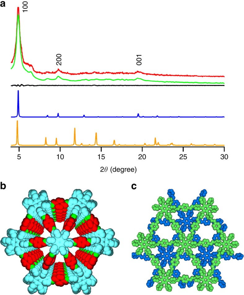
Covalent organic frameworks (COFs) are an emerging class of highly ordered porous polymers with many potential applications. They are currently designed and synthesized through hexagonal and tetragonal topologies, limiting the access to and exploration of new structures and properties. Here, we report that a triangular topology can be developed for the rational design and synthesis of a new class of COFs. The triangular topology features small pore sizes down to 12 Å, which is among the smallest pores for COFs reported to date, and high π-column densities of up to 0.25 nm(-2), which exceeds those of supramolecular columnar π-arrays and other COF materials. These crystalline COFs facilitate π-cloud delocalization and are highly conductive, with a hole mobility that is among the highest reported for COFs and polygraphitic ensembles.


Figures

Figure 1
Figure 1. Design of topology diagrams and synthesis of trigonal COFs.
(a) Topology diagrams for COFs and their pore size and π-column density. (b) Schematic representation of the synthesis of imine-linked triangular HPB-COF, together with its model reaction. (c) Propeller-shaped HPB building block. (d) Schematic representation of the synthesis of imine-linked triangular HBC-COF, together with its model reaction. (e) HBC building block.
Figure 2
Figure 2. Crystal structure of HPB-COF.
(a) XRD patterns of experimentally observed (red curve), Pawley refined pattern (green curve), their difference (black curve), eclipsed hybrid AA stacking mode (blue curve) and staggered AB stacking mode (orange curve). The crystal facets are shown with indices on the peaks. (b) View of the eclipsed hybrid AA stacking structure. (c) View of the staggered AB stacking structure.
Figure 3
Figure 3. Crystal structure of HBC-COF.
(a) XRD patterns of experimentally observed (red curve), Pawley refined pattern (green curve), their difference (black curve), 0.8 Å slipped AA stacking mode (blue curve) and staggered AB stacking mode (orange curve). The crystal facets are shown with indices on the peaks. (b) View of the 0.8 Å slipped AA stacking structure. (c) View of the staggered AB stacking structure.
Figure 4
Figure 4. Gas adsorption.
(a) Nitrogen sorption isotherm curve of HPB-COF (filled circles for adsorption and open circles for desorption). (b) Pore size distribution profile of HPB-COF. (c) Nitrogen sorption isotherm curve of HBC-COF (filled circles for adsorption and open circles for desorption). (d) Pore size distribution profile of HBC-COF.
Figure 5
Figure 5. Stability.
(a,b) XRD patterns of HPB-COF upon 1-day treatment under different conditions at (a) 25 °C and (b) boiling temperatures (heating at 100 °C). (c,d) XRD patterns of HBC-COF upon 1-day treatment under different conditions at (c) 25 °C and (d) boiling temperatures (heating at 100 °C).
Figure 6
Figure 6. π-Electronic and conducting properties.
(a) Solid-state electronic absorption spectra of HPB-COF (solid curve) and HPB (dotted curve). Inset: a photo of the HPB-COF sample. (b) Solid-state electronic absorption spectra of HBC-COF (solid curve) and HBC (dotted curve). Inset: a photo of the HBC-COF sample. (c) FP-TRMC profile of HPB-COF. (d) FP-TRMC profile of HBC-COF. (e) Photocurrent generation of spin coated HBC-COF on a comb-type gold electrode device (electrode gap=5 μm) at different bias voltages (2, 4 and 7 V). (f) IV curve of HBC-COF on the comb-type gold electrode device.

References

    1. Côté A. P. et al.. Porous, crystalline, covalent organic frameworks. Science 310, 1166–1170 (2005). - PubMed
    1. Feng X., Ding X. & Jiang D. Covalent organic frameworks. Chem. Soc. Rev. 41, 6010–6022 (2012). - PubMed
    1. Ding S.-Y. & Wang W. Covalent organic frameworks (COFs): from design to applications. Chem. Soc. Rev. 42, 548–568 (2013). - PubMed
    1. Wu D. et al.. Design and preparation of porous polymers. Chem. Rev. 112, 3959–4015 (2012). - PubMed
    1. Furukawa H. & Yaghi O. M. Storage of hydrogen, methane, and carbon dioxide in highly porous covalent organic frameworks for clean energy applications. J. Am. Chem. Soc. 131, 8875–8883 (2009). - PubMed

Publication types