

doi: 10.1364/OE.23.016142.
Open-top selective plane illumination microscope for conventionally mounted specimens
- PMID: 26193587
- PMCID: PMC4523553
- DOI: 10.1364/OE.23.016142
Item in Clipboard
Open-top selective plane illumination microscope for conventionally mounted specimens
Opt Express.
.
Abstract
We have developed a new open-top selective plane illumination microscope (SPIM) compatible with microfluidic devices, multi-well plates, and other sample formats used in conventional inverted microscopy. Its key element is a water prism that compensates for the aberrations introduced when imaging at 45 degrees through a coverglass. We have demonstrated its unique high-content imaging capability by recording Drosophila embryo development in environmentally-controlled microfluidic channels and imaging zebrafish embryos in 96-well plates. We have also shown the imaging of C. elegans and moving Drosophila larvae on coverslips.
Figures
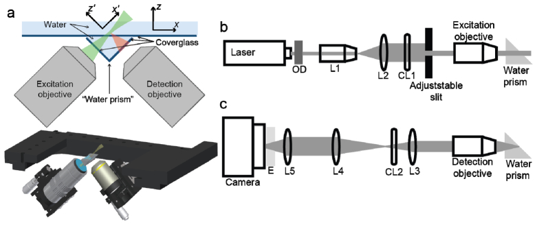
Imaging with open-top SPIM (a) Schematic drawing of open-top SPIM with the two objectives beneath the sample stage. Beneath the 2D drawing we show a 3D rendering of the microscope. (b) Detailed excitation path. The laser passes through an optical density filter (OD), a 7 × beam expander consisting of a 10 × objective (L1, RMS10X, Thorlabs) and a 75 mm lens (L2, AC254-075-A, Thorlabs), a 200 mm focal length cylindrical lens (CL1, LJ1653RM-A, Thorlabs), an adjustable slit aperture, and a 20 × 0.42NA objective before going through the water prism and into the sample. (c) Emission path. The light is collected through the water prism by a 10 × 0.3NA objective, goes through the tube lens (L3, AC254-200-A, Thorlabs), the aberration-correcting cylindrical lens (CL2, SCX-50.8-5000.0, Melles Griot), a pair of lenses relaying the image to the camera (L4 and L5, AC254-075-A-ML and AC254-150-A-ML, Thorlabs), and an emission filter (E, ET525/50 or ET595/50, Chroma).
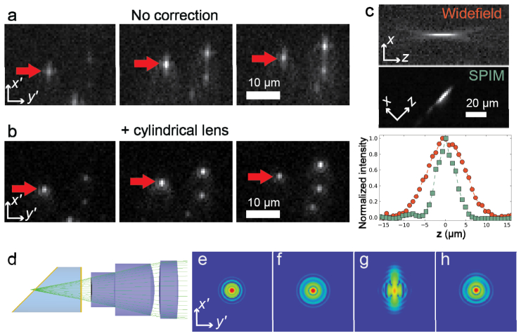
Characterization of the open-SPIM. (a) Three images of 200 nm fluorescent beads embedded in agarose from a scan of the sample. Between each frame the sample has moved 2.5 μm in x. The shape of the PSF clearly shows astigmatism. (b) Same beads with the cylindrical lens inserted. (c) Comparison of the PSF for the same 10 × 0.3 NA objective used in a widefield microscope and in our open-top SPIM. (d) Rendering of water prism and the first three elements of an objective lens used in Zemax ray tracing software for computing the Huygen’s PSFs shown in (e)-(h). The PSFs are displayed on with a log scale and cover a 330 × 330 μm2 area under the following conditions: (e) when imaging 500 μm into water past a coverslip; (f) same as (e) with an additional 6 mm of water plus an additional coverslip between the objective and focal plane; (g) same as (f) but when the coverslip closest to the focal plane is tilted 45°; and (h) same as (g) but with a 10 m focal length cylindrical lens inserted after the tube lens.
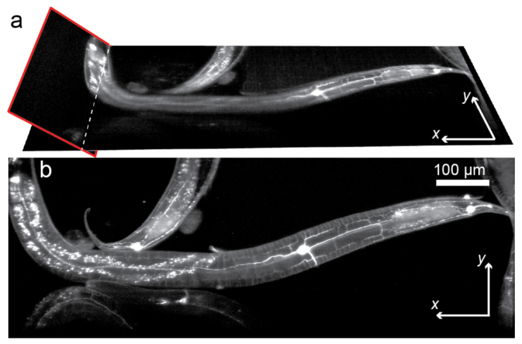
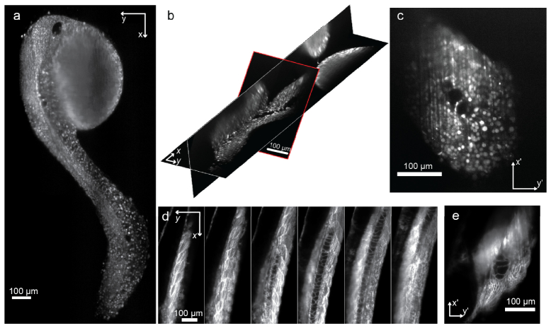
(a) Two slices through volumetric data of C. Elegans with PVD sensory neurons labeled with GFP. The slice outlined in red shows the raw camera image prior to any transformation. The other slice is an x-y section of the transformed volumetric data. (b) z-projection of data shown in (a) (see Media 1 and Media 2 ).
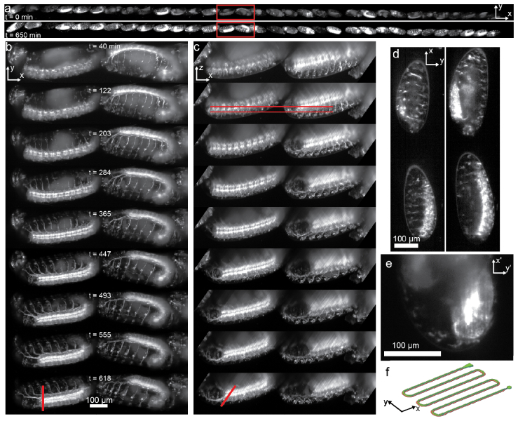
Parallel imaging of developing Drosophila embryos. (a) The z-projections of 32 Drosophila embryos that have been loaded into an approximately 14 mm section of a microfluidic channel. Only every 10th frame was used to generate the figure. A z-projection is shown at t = 0 (top) and at t = 650 min. (bottom). (b) The two embryos in the red box in (a) are shown at different times. The images again display z-projections but all frames acquired were used. (c) The same embryos and same time points as (b) are shown as y-projections. (d) Two slices in the x-y plane are shown corresponding to the red lines in (c) (see Media 3 ). (e) Image of embryo as acquired by camera and corresponding to the position indicated by the red lines in the last time point in (b) and (c). (f) Shown is a drawing of the microfluidic channel used.
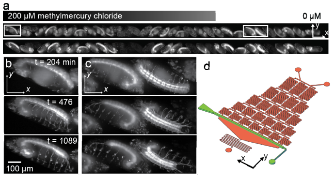
Imaging of developing Drosophila (a) Shown are z-projections of 32 Drosophila embryos loaded into a straight microfluidic channel along which a decreasing gradient in methylmercury chloride runs from left to right at time t = 0 (top) and t = 1089 min. (bottom). Only every 6th frame recorded was used to generate the projections. (b) The embryos in the left red box in (a) at different time points. The images again display z-projections but all frames acquired were used. (c) The z-projections of the embryo in the right red box at the same times points as (b) (see Media 4 ). (d) The schematic drawing of the microfluidic device shows the embryo-containing channel in green and the gradient generation channels in orange.
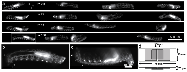
Imaging crawling Drosophila larvae (a) z-projections of four moving first instar larvae at different time points. (b) A z-projection of the larva highlighted. (c) A y-projection of the same larva shown in (b). (d) Sketch of slide and coverslips used to create channel to hold moving larvae.
Imaging zebrafish in 96-well plates (a) One x-y slice of a 48 hpf zebrafish in a 96-well plate. All cell nuclei are labeled with mRFP. (b) Multiple slices from the same embryo shown in (a). The slice outlined in red is the raw camera image before any transformations. The other two slices show an x-y and x-z cut. (c) An image of the same embryo as recorded on the camera. (d) Six x-y slices through the tail of a zebrafish with tdTomato labeling of the cell membranes. Each slice is spaced 23 μm apart in z. (e) An image as recorded by the camera of the same embryo as shown in (d) (see Media 5 ).
References
-
- Dodt H.-U., Leischner U., Schierloh A., Jährling N., Mauch C. P., Deininger K., Deussing J. M., Eder M., Zieglgänsberger W., Becker K., “Ultramicroscopy: three-dimensional visualization of neuronal networks in the whole mouse brain,” Nat. Methods 4(4), 331–336 (2007).10.1038/nmeth1036 - DOI - PubMed
-
- Wu Y., Ghitani A., Christensen R., Santella A., Du Z., Rondeau G., Bao Z., Colón-Ramos D., Shroff H., “Inverted selective plane illumination microscopy (iSPIM) enables coupled cell identity lineaging and neurodevelopmental imaging in Caenorhabditis elegans,” Proc. Natl. Acad. Sci. U.S.A. 108(43), 17708–17713 (2011).10.1073/pnas.1108494108 - DOI - PMC - PubMed
Publication types
MeSH terms
Grants and funding
LinkOut - more resources
Full Text Sources
Other Literature Sources
Molecular Biology Databases
