Actively Decoupled Transmit-Receive Coil-Pair for Mouse Brain MRI
- PMID: 26207105
- PMCID: PMC4509595
- DOI: 10.1002/cmr.b.20124
Actively Decoupled Transmit-Receive Coil-Pair for Mouse Brain MRI
Abstract
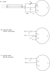
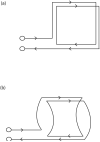
A low-cost, high performance RF coil-pair for MR imaging of mouse brain is described. A surface receiving coil is used for high spin-sensitivity, while a larger transmit coil, located outside the mouse holder, delivers good B1 uniformity across the brain with reasonable efficiency. The volume coil is constructed with an open architecture, making experimental setup easy and providing clear access to the head of the mouse. Each coil is switched between active and inactive modes using PIN diodes driven by a small amplifier external to the spectrometer. Because of this active decoupling, there is no requirement for orthogonal orientation of the coils. The coil pair is platform independent, requiring only a transmit/receive (T/R) signal to switch the amplifier that drives the PIN diodes, and can therefore be used with virtually any commercial or home-built MR scanner.
Figures


Similar articles
-
Comparison of MEMS switches and PIN diodes for switched dual tuned RF coils.Magn Reson Med. 2018 Oct;80(4):1746-1753. doi: 10.1002/mrm.27156. Epub 2018 Mar 9. Magn Reson Med. 2018. PMID: 29524235 Free PMC article.
-
Active decoupling of RF coils using a transmit array system.MAGMA. 2015 Dec;28(6):565-76. doi: 10.1007/s10334-015-0497-0. Epub 2015 Aug 5. MAGMA. 2015. PMID: 26239631
-
4 T actively detunable transmit/receive transverse electromagnetic coil and 4-channel receive-only phased array for (1)H human brain studies.Magn Reson Med. 2004 Dec;52(6):1459-64. doi: 10.1002/mrm.20264. Magn Reson Med. 2004. PMID: 15562466
-
An eight-channel transmit/receive multipurpose coil for musculoskeletal MR imaging at 7 T.Med Phys. 2010 Dec;37(12):6368-76. doi: 10.1118/1.3517176. Med Phys. 2010. PMID: 21302794
-
High-performance radiofrequency coils for (23)Na MRI: brain and musculoskeletal applications.NMR Biomed. 2016 Feb;29(2):96-106. doi: 10.1002/nbm.3379. Epub 2015 Sep 24. NMR Biomed. 2016. PMID: 26404631 Free PMC article. Review.
Cited by
-
RGS4 controls renal blood flow and inhibits cyclosporine-mediated nephrotoxicity.Am J Transplant. 2010 Feb;10(2):231-41. doi: 10.1111/j.1600-6143.2009.02930.x. Epub 2009 Dec 2. Am J Transplant. 2010. PMID: 19958325 Free PMC article.
-
Diffusion basis spectrum imaging detects subclinical traumatic optic neuropathy in a closed-head impact mouse model of traumatic brain injury.Front Neurol. 2023 Dec 13;14:1269817. doi: 10.3389/fneur.2023.1269817. eCollection 2023. Front Neurol. 2023. PMID: 38152638 Free PMC article.
-
White-matter diffusion fMRI of mouse optic nerve.Neuroimage. 2013 Jan 15;65:209-15. doi: 10.1016/j.neuroimage.2012.10.021. Epub 2012 Oct 18. Neuroimage. 2013. PMID: 23085108 Free PMC article.
-
A Modified Quadrature Birdcage Coil Incorporated With a Curved Feature for In Ovo MR Imaging.IEEE Open J Eng Med Biol. 2024 Jun 28;5:534-541. doi: 10.1109/OJEMB.2024.3420231. eCollection 2024. IEEE Open J Eng Med Biol. 2024. PMID: 39050970 Free PMC article.
-
Test-Retest Performance of a 1-Hour Multiparametric MR Image Acquisition Pipeline With Orthotopic Triple-Negative Breast Cancer Patient-Derived Tumor Xenografts.Tomography. 2019 Sep;5(3):320-331. doi: 10.18383/j.tom.2019.00012. Tomography. 2019. PMID: 31572793 Free PMC article.
References
-
- Benveniste H, Ma Y, Dhawan J, Gifford A, Smith SD, Feinstein I, Du C, Grant SC, Hof PR. Anatomical and functional phenotyping of mice models of Alzheimer's disease by MR microscopy. Ann N Y Acad Sci. 2007;1097:12–29. - PubMed
-
- Jack CR, Jr., Marjanska M, Wengenack TM, Reyes DA, Curran GL, Lin J, Preboske GM, Poduslo JF, Garwood M. Magnetic resonance imaging of Alzheimer's pathology in the brains of living transgenic mice: a new tool in Alzheimer's disease research. Neuroscientist. 2007;13:38–48. - PubMed
-
- Budde MD, Kim JH, Liang HF, Schmidt RE, Russell JH, Cross AH, Song SK. Toward accurate diagnosis of white matter pathology using diffusion tensor imaging. Magn Reson Med. 2007;57:688–695. - PubMed
-
- Politi LS, Bacigaluppi M, Brambilla E, Cadioli M, Falini A, Comi G, Scotti G, Martino G, Pluchino S. Magnetic-resonance-based tracking and quantification of intravenously injected neural stem cell accumulation in the brains of mice with experimental multiple sclerosis. Stem Cells. 2007;25:2583–92. - PubMed
Grants and funding
LinkOut - more resources
Full Text Sources
