. 2016 Jul;76(1):32-44.
doi: 10.1002/mrm.25839. Epub 2015 Jul 24.

Dual-polarity GRAPPA for simultaneous reconstruction and ghost correction of echo planar imaging data

Affiliations

Dual-polarity GRAPPA for simultaneous reconstruction and ghost correction of echo planar imaging data

W Scott Hoge et al. Magn Reson Med. 2016 Jul.

Abstract

Purpose: The purpose of this study was to seek improved image quality from accelerated echo planar imaging (EPI) data, particularly at ultrahigh fields. Certain artifacts in EPI reconstructions can be attributed to nonlinear phase differences between data acquired using frequency-encoding gradients of alternating polarity. These errors appear near regions of local susceptibility gradients and typically cannot be corrected with conventional Nyquist ghost correction (NGC) methods.

Methods: We propose a new reconstruction method that integrates ghost correction into the parallel imaging data recovery process. This is achieved through a pair of generalized autocalibrating partially parallel acquisitions (GRAPPA) kernels that operate directly on the measured EPI data. The proposed dual-polarity GRAPPA (DPG) method estimates missing k-space data while simultaneously correcting inherent EPI phase errors.

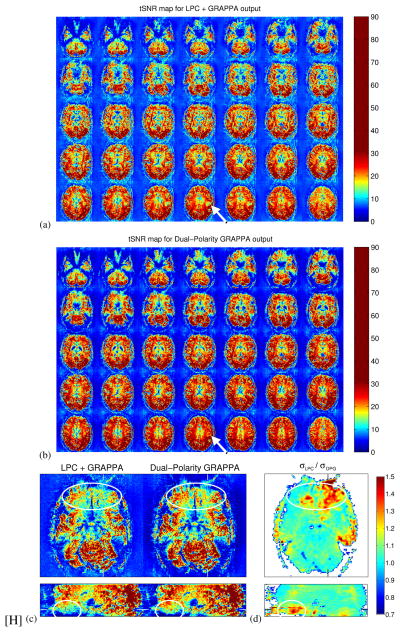
Results: Simulation results showed that standard NGC is incapable of correcting higher-order phase errors, whereas the DPG kernel approach successfully removed these errors. The presence of higher-order phase errors near regions of local susceptibility gradients was demonstrated with in vivo data. DPG reconstructions of in vivo 3T and 7T EPI data acquired near these regions showed a marked improvement over conventional methods.

Conclusion: This new parallel imaging method for reconstructing accelerated EPI data shows better resilience to inherent EPI phase errors, resulting in higher image quality in regions where higher-order EPI phase errors commonly occur. Magn Reson Med 76:32-44, 2016. © 2015 Wiley Periodicals, Inc.

Keywords: GESTE; Nyquist ghost correction; artifact correction; fMRI; oblique ghosts; parallel imaging.


Figures

Figure 1
Figure 1
Conventional GRAPPA and the proposed DPG for a kernel of size Nx = 5 and Ny = 4. (a) Conventional GRAPPA reconstruction model, in which acquired k-space lines from a single frame are used to estimate missing samples. The underlying grid depicts the desired k-space sampling grid. (b) Proposed Dual-Polarity GRAPPA reconstruction model, in which data taken from two distinct frames of EPI data are combined to cancel phase errors while estimating missing samples. The intrinsic phase errors in EPI are depicted by offsets in both kx and ky between the acquired sample locations and the desired sampling grid. Gray dots represent source points; black dots represent target points. For simplicity, the coil dimension is not shown.
Figure 2
Figure 2
Analysis and synthesis signal flow diagrams for the Dual-Polarity GRAPPA algorithm for R = 2 data. On the analysis/training side, three fully-sampled data sets {RO+, RO, target} are used to calibrate each DPG kernel. The six possible DPG kernels for an R = 2 configuration are shown, with shaded circles indicating source and target points. The shading corresponds to RO+ data (dark gray), RO data (light gray), and target data (black). On the synthesis/application side, four kernels are chosen to reconstruct the accelerated k-space data. The kernels shown match particular patterns of RO+ and RO samples within the acquired accelerated EPI data. Note that each line of reconstructed k-space is synthesized by at least one of the DPG kernels. Further, some kernels are redundant, in that one may be able to synthesize certain lines of k-space using more than one kernel. Thus, for R = 2, only four kernels are needed out of the six possible kernels.
Figure 3
Figure 3
Results from the phase error simulation. Each row shows the simulated phase error introduced to the data (left), and the corresponding reconstructed image and image error for both LPC+GRAPPA (middle) and Dual-Polarity GRAPPA (right). The phase errors were: (a) a constant plus linear; (b) a constant plus quadratic; and (c) a constant plus cubic, respectively. The last row, (d), shows the result of simulating all phase errors (constant plus 1st, 2nd, and 3rd order) simultaneously.
Figure 4
Figure 4
Images from an anthropomorphic head phantom, showing the ability of DPG to remove the interference pattern artifact in both (a) unaccelerated (i.e., R = 1) and (b) R = 4 data.
Figure 5
Figure 5
Phase differences between standard RO+ and RO navigator lines used in conventional NGC methods, shown in the hybrid xky domain and displayed across all coil channels and image slices. The line plot in each panel shows the phase differences for a single coil channel in two slices: (a) coil channel 8 in slices 6 and 32, (b) coil channel 19 in slices 6 and 32, and (c) coil channel 8 in slices 12 and 32. (The axial image corresponding to slice 12 of this dataset is also shown in Fig. 6(a).) Lower slice numbers correspond to more inferior slice locations. Non-linear phase differences are evident in many coils within the inferior slice locations, which are proximal to the region of B0 inhomogeneity. The intensity of the circles in the line plot correspond to the magnitude of the navigator signal, with higher intensity represented by darker circles—the navigator signal magnitude is used as a weighting term in the LPC method to de-emphasize locations in hybrid space where the navigator signal is less reliable on account of the low sensitivity of the coil.
Figure 6
Figure 6
Comparisons between conventional LPC+GRAPPA and DPG reconstructions, focused on images near regions with local susceptibility gradients. Four 7T subjects (a–d) with R = 3 acceleration and two additional 7T subjects (e–f) with R = 4 acceleration are shown. White dashes show the relative location of the alternate image. Interference pattern artifacts are highlighted with arrows in the axial images, and by the white ellipse in the sagittal views.
Figure 7
Figure 7
Comparison of tSNR maps for the R = 3 7T data set shown in Fig. 6(a), windowed to emphasize the lower-third of the dynamic range. (a) tSNR for 35 slices reconstructed by the LPC+GRAPPA method; (b) tSNR for the same data reconstructed using DPG. Arrows indicate example focal regions where tSNR is notably higher with DPG than in the LPC+GRAPPA reconstruction, both above the paranasal sinuses and a region near the ear canals. (c) A highlight of one axial and one sagittal-reformatted slice emphasizing regions (indicated by ellipses) with interference pattern artifacts. (c) An image of the ratio between the LPC+GRAPPA and DPG temporal signal variance, highlighting regions were DPG outperforms LPC+GRAPPA in terms of tSNR.
Figure 8
Figure 8
Results from the experiment to demonstrate DPG sensitivity to kernel size and integrating conventional phase correction into the DPG reconstruction as a preprocessing step. (a–c) DPG k-space calibration data for one coil, demonstrating a case with a large coordinate shift along kx between RO+ and RO. (d–f) Image reconstructions from three different scenarios: (d) a small DPG kernel; (e) LPC combined with the small kernel; and (f) a large DPG kernel. The images demonstrate LPC and DPG are compatible—LPC can be used to first estimate the linear component and correct the large shift, while DPG can be used afterward to mitigate higher-order phase error effects.
Figure 9
Figure 9
A demonstration of the DPG method correcting oblique EPI ghosts caused by 2D phase errors. (a) A 2D phase error map (in radians) calculated as the phase difference between the RO+ and RO frames of the GESTE ACS data. A phase difference trend is seen in the vertical phase encoding (y) direction, indicating the presence of alternating phase errors between odd and even ky lines. (b) Image reconstructions of the corresponding unaccelerated (R = 1) data. The top row presents images with typical windowing. The bottom row presents the same images with windowing adjusted to better visualize ghost regions. The LPC+GRAPPA reconstruction shows an oblique ghost, which is properly corrected in the DPG reconstruction.
Figure 10
Figure 10
Signal flow diagram for GESTE processing of multi-shot EPI calibration data. In the first stage (left), all of the segments are phase corrected and averaged, in order to generate temporary GRAPPA coefficients, c. In the second stage (top right), each of the segments are ghost-corrected using PLACE. In the third stage (bottom right), GESTE is used to combine the PLACE-corrected segments and generate the target calibration data. Example images at various points in each stage are shown in (a–d), with the left half showing typical windowing, and the right half showing the lowest 10% of the image signal.

References

    1. Keil B, Wald LL. Massively parallel MRI detector arrays. Journal of Magnetic Resonance. 2013;229:75–89. - PMC - PubMed
    1. Feiweier T. Magnetic resonance method and apparatus to determine phase correction parameters. 8,497,681 US Patent. 2013
    1. de Zwart JA, van Gelderen P, Golay X, Ikonomidou VN, Duyn JH. Accelerated parallel imaging for functional imaging of the human. NMR in Biomedicine. 2006;19(3):342–351. - PubMed
    1. Wald LL, Polimeni JR. High-speed, high-resolution acquisitions. In: Toga AW, editor. Brain Mapping: An Encyclopedic Reference. San Diego, CA: Academic Press; 2015.
    1. Skare S, Newbould RD, Clayton DB, Albers GW, Nagle S, Bammer R. Clinical multishot DW-EPI through parallel imaging with considerations of susceptibility, motion, and noise. Magn Reson Med. 2007;57(5):881–890. - PMC - PubMed

Publication types

MeSH terms