. 2015 Jul 9;9(4):044104.
doi: 10.1063/1.4926583. eCollection 2015 Jul.

Microfluidic reflow pumps

Affiliations

Microfluidic reflow pumps

Bryan Haslam et al. Biomicrofluidics. .

Abstract

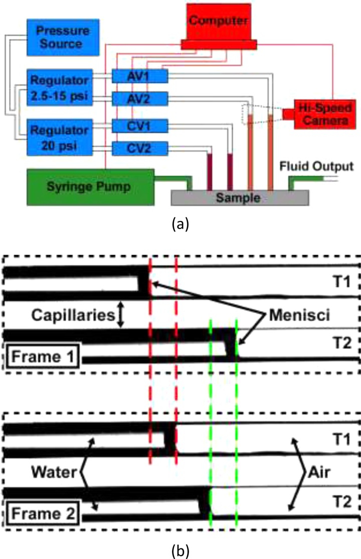
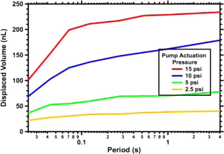
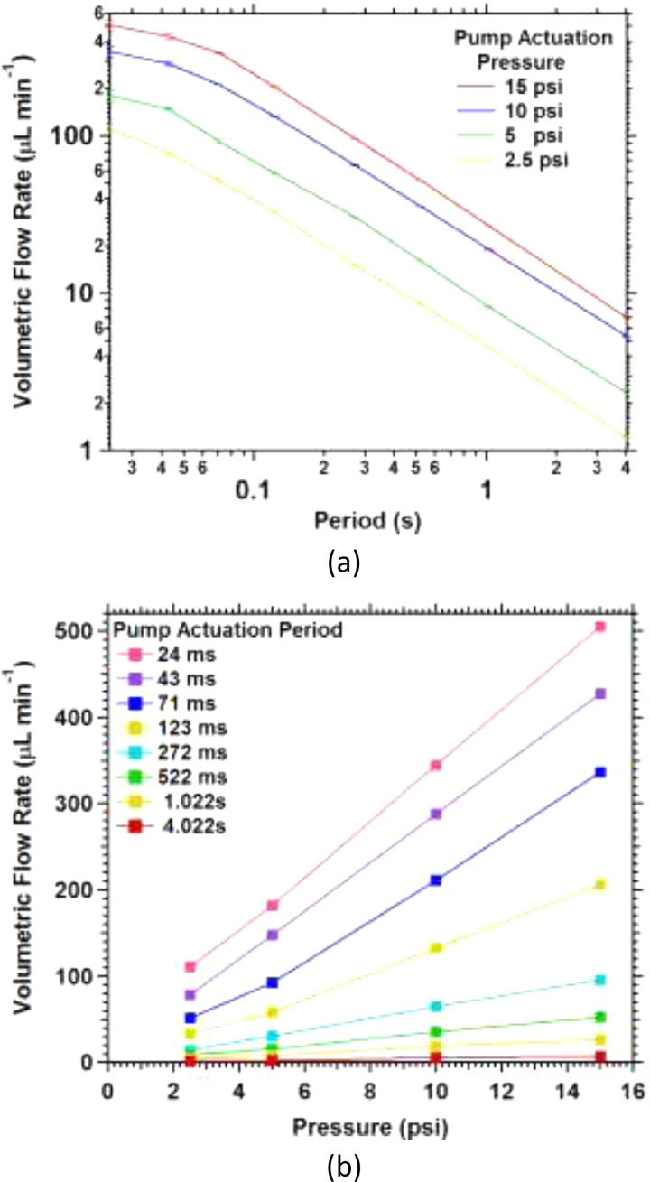
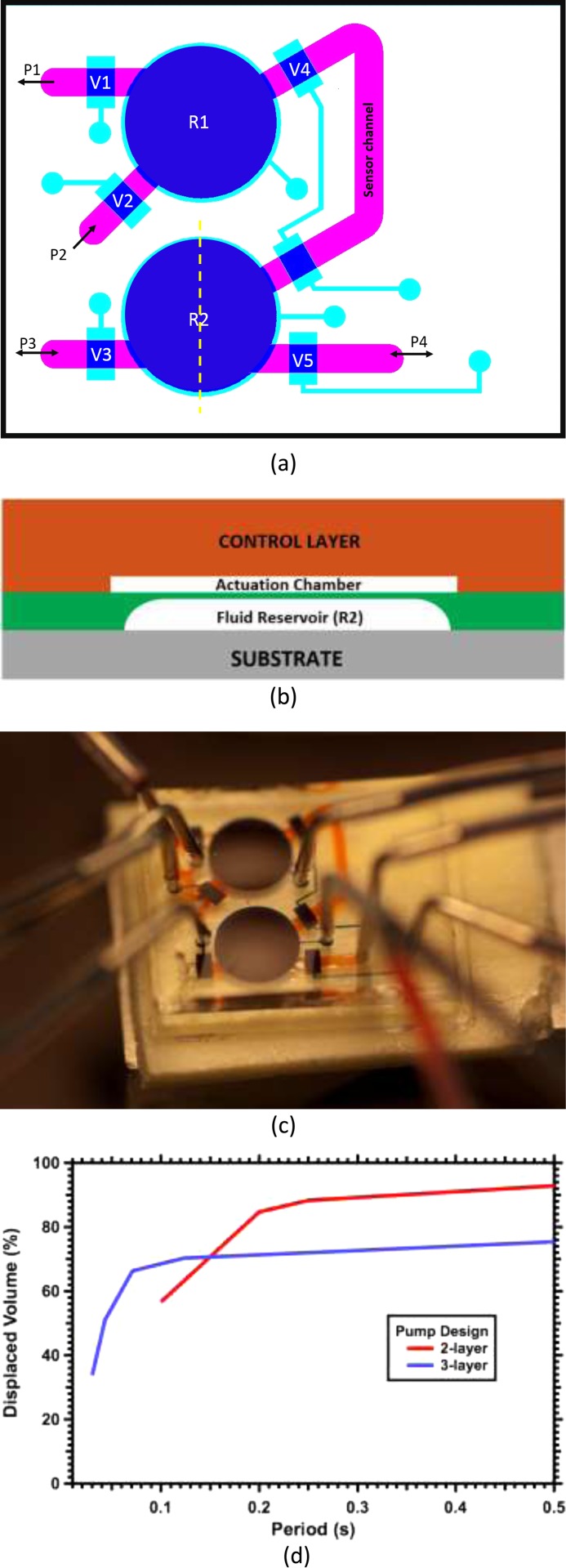
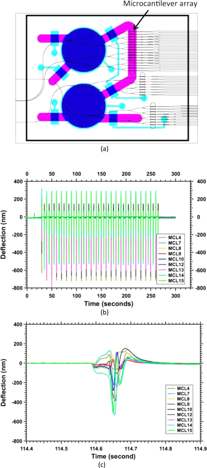
A new microfluidic pump, termed a reflow pump, is designed to operate with a sub-μl sample volume and transport it back and forth between two pneumatically actuated reservoirs through a flow channel typically containing one or more sensor surfaces. The ultimate motivation is to efficiently use the small sample volume in conjunction with convection to maximize analyte flux to the sensor surface(s) in order to minimize sensor response time. In this paper, we focus on the operational properties of the pumps themselves (rather than the sensor surfaces), and demonstrate both two-layer and three-layer polydimethylsiloxane reflow pumps. For the three-layer pump, we examine the effects of reservoir actuation pressure and actuation period, and demonstrate average volumetric flow rates as high as 500 μl/min. We also show that the two-layer design can pump up to 93% of the sample volume during each half period and demonstrate integration of a reflow pump with a single-chip microcantilever array to measure maximum flow rate.


Figures

FIG. 1.
FIG. 1.
Reflow pump schematic diagrams. (a) Top view with fluid channel in green, control channels and valves in red, and actuation channels and chambers in orange. (b) and (c) Cross section views along dashed lines indicated in (a). See text for details.
FIG. 2.
FIG. 2.
Photographs of fabricated device with coloring matching Fig. 1: (a) a top view with R1 actuated as seen by the orange fluid in the actuation chamber completely displacing the green fluid in the reservoir, R2 is filled with green fluid and the actuation chamber is not actuated. (b) A side view of the PDMS device clamped with the glass piece on top and the appropriate stainless steel and PTFE tubing connections. R1 is again actuated while R2 is not.
FIG. 3.
FIG. 3.
(a) Schematic diagram of experimental setup including the menisci being tracked by the hi-speed camera. (b) Two sample frames from a hi-speed video clip demonstrating the movement of the menisci.
FIG. 4.
FIG. 4.
Meniscus position as a function of time for the given pressures with three different periods: (a) 1.022 s, (b) 0.123 s, and (c) 0.030 s.
FIG. 5.
FIG. 5.
Average displaced reservoir volume during one half period.
FIG. 6.
FIG. 6.
Average volumetric flow rate as a function of (a) actuation period and (b) actuation pressure.
FIG. 7.
FIG. 7.
Schematic (a) top view and (b) side view of two-layer pump design. The side view is through the dashed line through reservoir R2 in (a). (c) Photo of fabricated two-layer pump design. (d) Displaced volume from a pump reservoir as percent of total reservoir volume for two-layer and three-layer pump designs. In both cases, the actuation pressure is 15 psi. The membrane reservoir membrane thicknesses are 17 and 50 μm, respectively.
FIG. 8.
FIG. 8.
(a) Schematic illustration of two-layer pump integrated on top of 10 mm × 14 mm silicon-on-insulator chip. The flow channel between the reservoirs is positioned over a microcantilever array capable of simultaneous photonic readout of each microcantilever's deflection. (b) Measured deflection for array of microcantilevers during 24 cycles of reflow pump operation. For this particular sample, nine working microcantilevers are monitored; the others in the array suffered from various fabrication defects. (c) Measured deflection during one half period of reflow pump operation.

References

    1. Mark D., Haeberle S., Roth G., von Stetten F., and Zengerle R., “Microfluidic lab-on-a-chip platforms: requirements, characteristics and applications,” Chem. Soc. Rev. 39, 1153 (2010).10.1039/b820557b - DOI - PubMed
    1. Whitesides G. M., “The origins and the future of microfluidics,” Nature 442, 368–373 (2006).10.1038/nature05058 - DOI - PubMed
    1. Squires T. M., Messinger R. J., and Manalis S. R., “Making it stick: convection, reaction and diffusion in surface-based biosensors,” Nat. Biotechnol. 26, 417–426 (2008).10.1038/nbt1388 - DOI - PubMed
    1. Rupp J., Schmidt M., Münch S., Cavalar M., Steller U., Steigert J. et al., “Rapid microarray processing using a disposable hybridization chamber with an integrated micropump,” Lab Chip 12, 1384 (2012).10.1039/c2lc21110f - DOI - PubMed
    1. Jeong O. C. and Konishi S., “Fabrication and drive test of pneumatic PDMS micro pump,” Sens. Actuators, A 135, 849–856 (2007).10.1016/j.sna.2006.09.012 - DOI

LinkOut - more resources