. 2015 Jul 28;15(8):18360-80.
doi: 10.3390/s150818360.

From Laser Scanning to Finite Element Analysis of Complex Buildings by Using a Semi-Automatic Procedure

Affiliations

From Laser Scanning to Finite Element Analysis of Complex Buildings by Using a Semi-Automatic Procedure

Giovanni Castellazzi et al. Sensors (Basel). .

Abstract

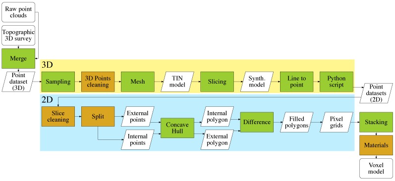
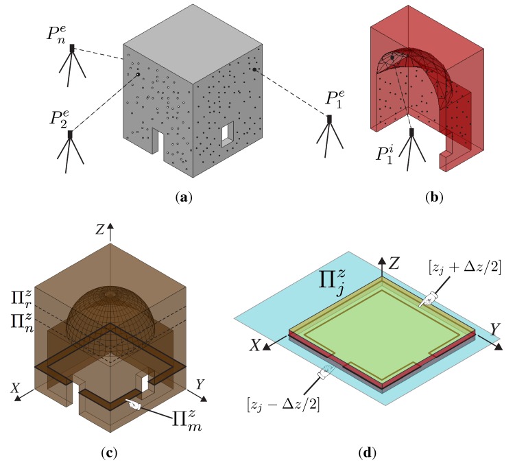
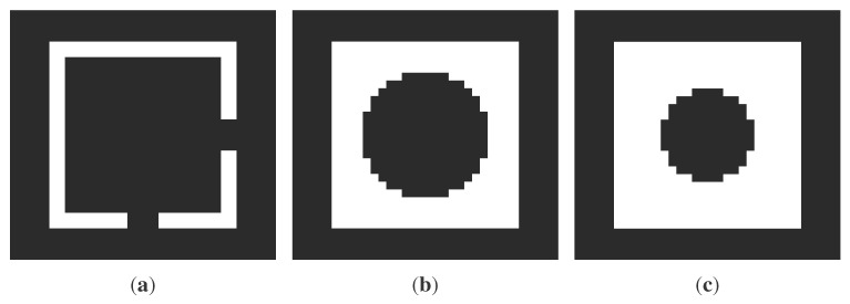
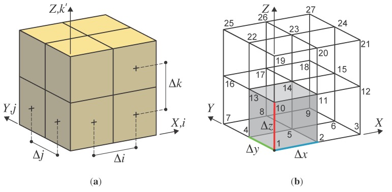
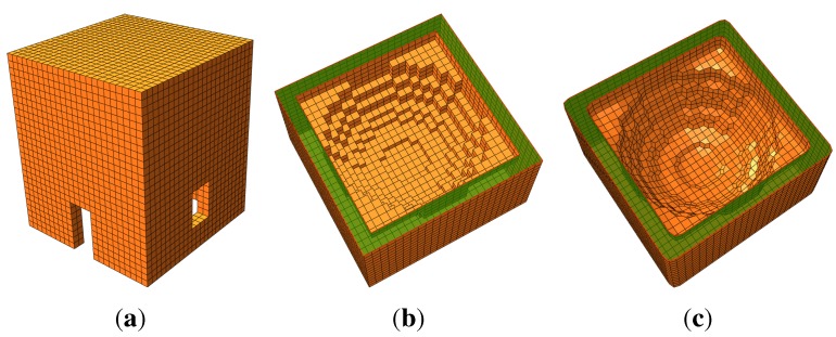
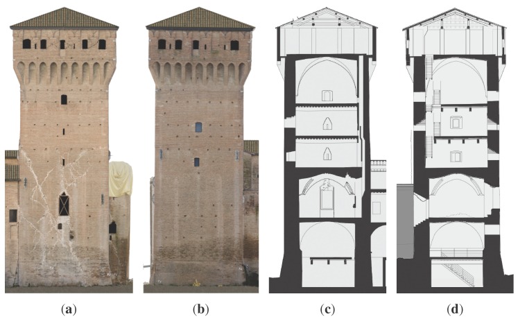
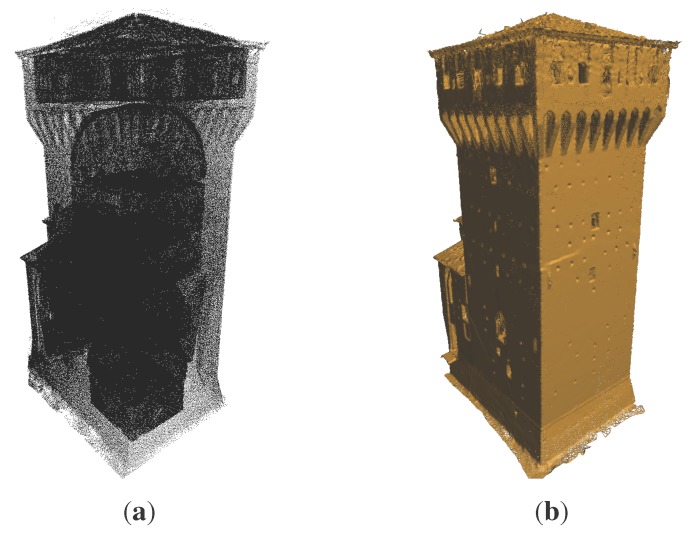
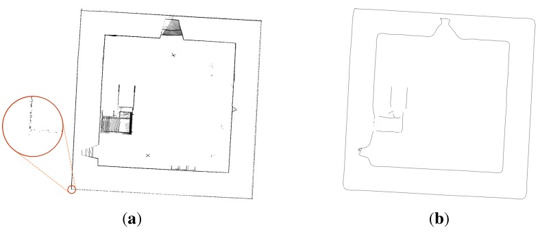
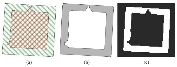
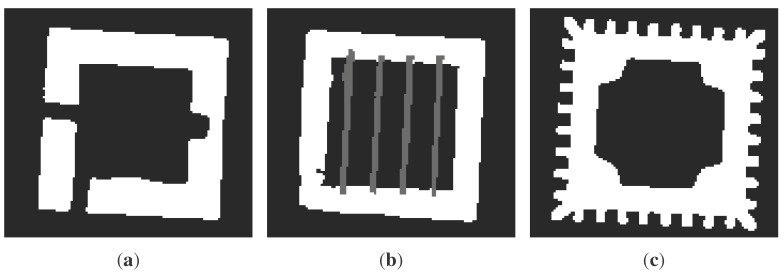
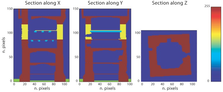
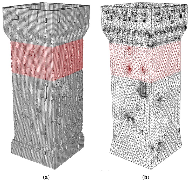
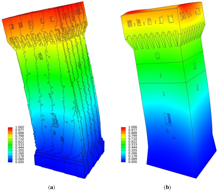
In this paper, a new semi-automatic procedure to transform three-dimensional point clouds of complex objects to three-dimensional finite element models is presented and validated. The procedure conceives of the point cloud as a stacking of point sections. The complexity of the clouds is arbitrary, since the procedure is designed for terrestrial laser scanner surveys applied to buildings with irregular geometry, such as historical buildings. The procedure aims at solving the problems connected to the generation of finite element models of these complex structures by constructing a fine discretized geometry with a reduced amount of time and ready to be used with structural analysis. If the starting clouds represent the inner and outer surfaces of the structure, the resulting finite element model will accurately capture the whole three-dimensional structure, producing a complex solid made by voxel elements. A comparison analysis with a CAD-based model is carried out on a historical building damaged by a seismic event. The results indicate that the proposed procedure is effective and obtains comparable models in a shorter time, with an increased level of automation.

Keywords: cultural heritage; finite element analysis; geometric modeling; historical buildings; structural analysis; terrestrial laser scanning.


Figures

Figure 1
Figure 1
Flowchart for the proposed method: completely automated procedures (green) and semi-automated or manual procedures (orange).
Figure 2
Figure 2
Visualization of the stacking layer sequence concept. (a) Point cloud survey of external façades; (b) point cloud survey of internal surfaces; (c) illustration of the m-th slice; (d) Πjz layer.
Figure 3
Figure 3
Two dimensional images obtained by slicing the structure illustrated in Figure 2: m, n and r represent three generic slices located at the zm, zn and zr coordinates respectively. (a) Πmz; (b) Πnz; (c) Πrz.
Figure 4
Figure 4
Voxel representation and finite element transformation: {i, j, k} and {X, Y, Z} are the indexes of the voxels’ three-dimensional matrix and the global coordinates of the structure, respectively. The coordinate k' means k' = Rk, where Ris the third size (along Z) of the voxels’ three-dimensional matrix (N × M × R). (a) Voxel indexes;(b) hexahedral elements.
Figure 5
Figure 5
Finite element mesh obtained by applying the procedure to the structure represented in Figure 2. (a) External restitution; (b) internal restitution; (c) smoothed internal restitution.
Figure 6
Figure 6
San Felice sul Panaro Fortress principal tower. (a) South front; (b) east front; (c) E-W section; (d) S-N section.
Figure 7
Figure 7
Three-dimensional models for Mastio tower. (a) Points; (b) triangular irregular network (TIN) mesh.
Figure 8
Figure 8
First part of the slicing workflow (3D data): the magnified portion shows the uneven density of the raw data. (a) Points within the Δz increment; (b) final processed slice of points.
Figure 9
Figure 9
Second part of the slicing workflow (2D data). (a) Internal (red), external (green); (b) filled slice; (c) bitmap: 116 × 107 pixels.
Figure 10
Figure 10
Examples of bitmap slices. (a) 42nd slice; (b) 84th slice; (c) 128th slice.
Figure 11
Figure 11
Visualization of the three-dimensional material matrix: voxels possess unitary dimension. Five materials (colors) are used to represent the structure according to the mechanical characterization given in Table 1.
Figure 12
Figure 12
Finite element discretization comparison; colors are set according to the material properties: gray and red colors are used to illustrate the masonry and the reinforced masonry elements, respectively. (a) CLOUD2FEM discretization; (b) CAD-based discretization.
Figure 13
Figure 13
Mode 1: bending mode shape. Displacements magnitude. (a) Voxel frequency = 1.9131 Hz; (b) CAD frequency = 1.9137 Hz.

References

    1. Vosselman G., Maas H.-G. Airborne and Terrestrial Laser Scanning. CRC; Boca Raton, FL, USA: 2010.
    1. Shan J., Toth C. Topographic Laser Ranging and Scanning: Principles and Processing. CRC; Boca Raton, FL, USA: 2008.
    1. Boehler W., Heinz G., Marbs A. The potential of non-contact close range laser scanners for cultural heritage recording. Int. Arch. Photogramm. Remote Sens. Spat. Inf. Sci. 2002;34:430–436.
    1. Núñez M.A., Pozuelo F.B. Evolution of the architectural and heritage representation. Landsc. Urban Plan. 2009;91:105–112. doi: 10.1016/j.landurbplan.2008.12.006. - DOI
    1. Dorninger P., Pfeifer N. A Comprehensive Automated 3D Approach for Building Extraction, Reconstruction, and Regularization from Airborne Laser Scanning Point Clouds. Sensors. 2008;8:7323–7343. doi: 10.3390/s8117323. - DOI - PMC - PubMed

LinkOut - more resources