Review
. 2015 Oct;24(10):1560-79.
doi: 10.1002/pro.2759. Epub 2015 Sep 18.

Energy coupling mechanisms of MFS transporters

Affiliations
Review

Energy coupling mechanisms of MFS transporters

Xuejun C Zhang et al. Protein Sci. 2015 Oct.

Abstract

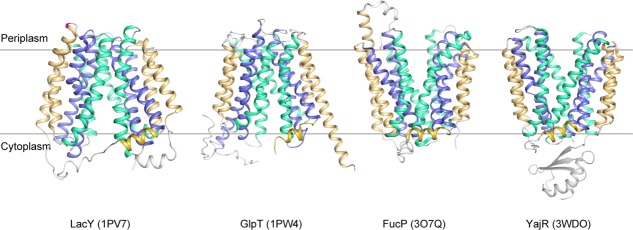
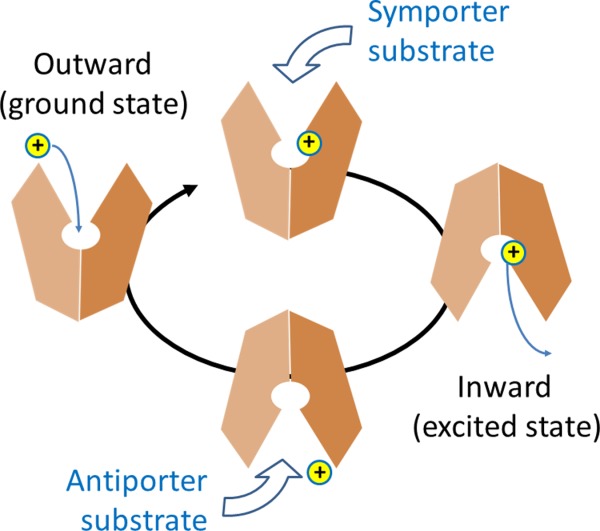
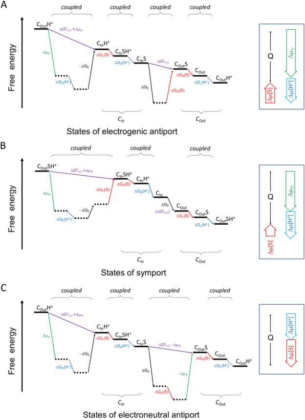
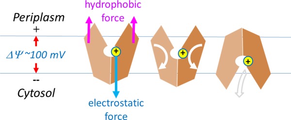
Major facilitator superfamily (MFS) is a large class of secondary active transporters widely expressed across all life kingdoms. Although a common 12-transmembrane helix-bundle architecture is found in most MFS crystal structures available, a common mechanism of energy coupling remains to be elucidated. Here, we discuss several models for energy-coupling in the transport process of the transporters, largely based on currently available structures and the results of their biochemical analyses. Special attention is paid to the interaction between protonation and the negative-inside membrane potential. Also, functional roles of the conserved sequence motifs are discussed in the context of the 3D structures. We anticipate that in the near future, a unified picture of the functions of MFS transporters will emerge from the insights gained from studies of the common architectures and conserved motifs.

Keywords: MFS transporters; energy coupling mechanisms; membrane potential; motif A.


Figures

Figure 1
Figure 1
Representative crystal structures of MFS transporters. LacY/1PV7, GlpT/1PW4, FucP/3O7Q, and YajR/3WDO are shown in ribbon diagrams. Cavity helices are colored in blue, rocker helices in cyan, and support helices as well as the amphipathic helices α6–7 in golden.
Figure 2
Figure 2
Schematic diagram of the transport cycle of MFS protein.
Figure 3
Figure 3
Schematic diagram of the energy landscape of MFS transporters. A: Electrogenic antiporter. B: Symporter. C: Electroneutral antiporter. The free-energy landscape plot describes the thermodynamic relationship between different states, without attention to kinetic issues. The plot must satisfy the First and Second Laws of thermodynamics. Horizontal lines represent states. Tilted lines represent transitions between states. Transitions associated with the proton are indicated in blue, those with the substrate in red, and those with ΔΨ in green. Subscripts L, R, D, and E stand for energy terms associated with loading, releasing, differential binding, and elastic, respectively. “I>O” and “O>I” stand for the CIn-to-COut and COut-to-CIn conformational changes, respectively. In principle, since the transport process cycles, choice of the starting point is arbitrary. In this sense the starting and ending states are identical, only being differed by the release of heat (Q) during one transport cycle. Thus, the end state must be below the starting state. Neighboring states may be coupled tightly. In such a case, their sequential order may be arbitrary. Locally, any transition of positive ΔG must be driven by a neighboring transition of a negative ΔG. (Also see Appendices).
Figure 4
Figure 4
Membrane potential-driving hypothesis. Conformational changes driven by protonation are depicted. Directions of physical movements are shown in arrows.
Figure 5
Figure 5
Coupling of substrate binding with protonation in symporters. Putative substrate binding site of E. coli YbgH (PDB ID: 4Q65). A model substrate (alafosfalin) is included based on superposition of a homologous complex crystal structure (4IKZ). Selected residues that are potentially important for substrate binding are shown in stick models. A cluster of polar residues (Q18, E21, Y22, and K118) potentially plays a role of coupling substrate binding with protonation at E21.
Figure 6
Figure 6
Active conformation of motif A of E. coli YajR. A: Side chains in motif A and Asp126 from the charge-relay triad are shown as stick models. Cα atoms of conserved Gly residues are shown as spheres. TM11 is colored from cyan at the N-terminal end to pink at the C-terminal end. B: Putative role of the inter-domain linker in regulating motif-A.
Figure 7
Figure 7
Structure and mechanism of the motif-B. A: Motif-B in the crystal structure of MdfA/4ZOW. Residues of the motif-B and surrounding conserved residues are shown in stick models. Backbone of the N- and C-domain is shown in tubes indicated in wheat and red, respectively. B: Schematic diagram of motif-B in regulating deprotonation.

References

    1. Marger MD, Saier MH., Jr. ( A major superfamily of transmembrane facilitators that catalyse uniport, symport and antiport. Trends Biochem Sci. 1993;18:13–20. - PubMed
    1. Law CJ, Maloney PC, Wang DN( Ins and outs of major facilitator superfamily antiporters. Ann Rev Microbiol. 2008;62:289–305. - PMC - PubMed
    1. Saier MH, Jr, Beatty JT, Goffeau A, Harley KT, Heijne WH, Huang SC, Jack DL, Jahn PS, Lew K, Liu J, Pao SS, Paulsen IT, Tseng TT, Virk PS( The major facilitator superfamily. J Mol Microbiol Biotechnol. 1999;1:257–279. - PubMed
    1. Brown S, Chang JL, Sadee W, Babbitt PC( A semiautomated approach to gene discovery through expressed sequence tag data mining: discovery of new human transporter genes. AAPS PharmSci. 2003;5:E1. - PMC - PubMed
    1. Poolman B, Konings WN( Secondary solute transport in bacteria. Biochim Biophys Acta. 1993;1183:5–39. - PubMed

Publication types

MeSH terms

Substances

LinkOut - more resources