

Investigation of Parallel Radiofrequency Transmission for the Reduction of Heating in Long Conductive Leads in 3 Tesla Magnetic Resonance Imaging
- PMID: 26237218
- PMCID: PMC4523176
- DOI: 10.1371/journal.pone.0134379
Investigation of Parallel Radiofrequency Transmission for the Reduction of Heating in Long Conductive Leads in 3 Tesla Magnetic Resonance Imaging
Abstract
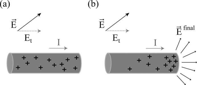
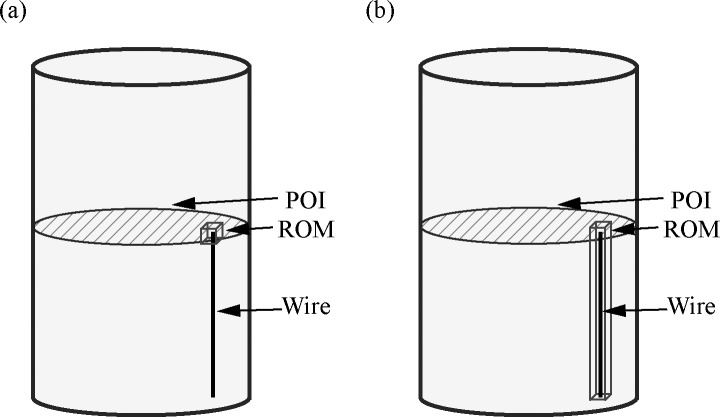
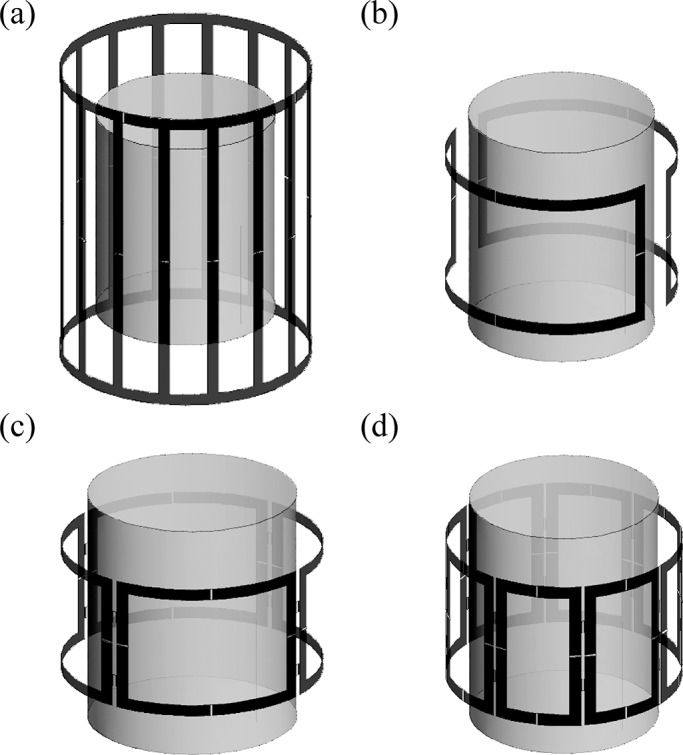
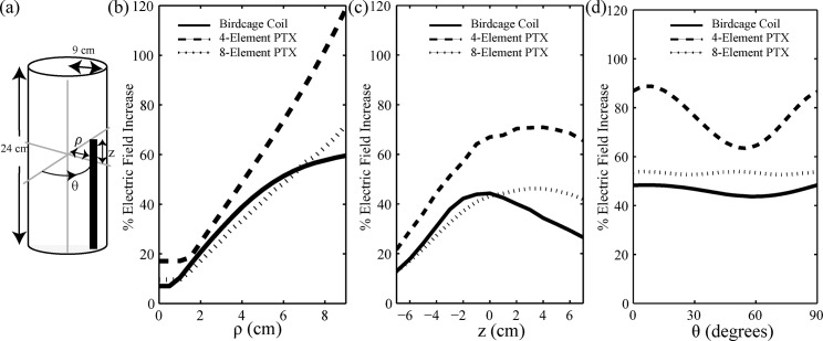
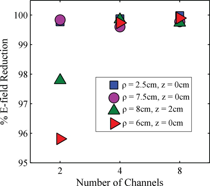
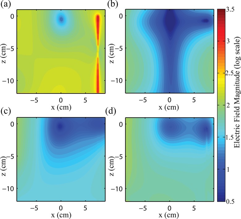
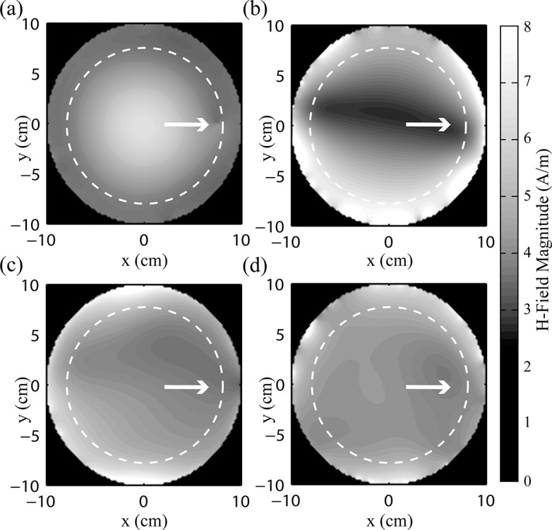
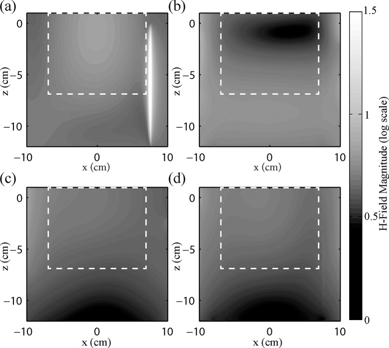
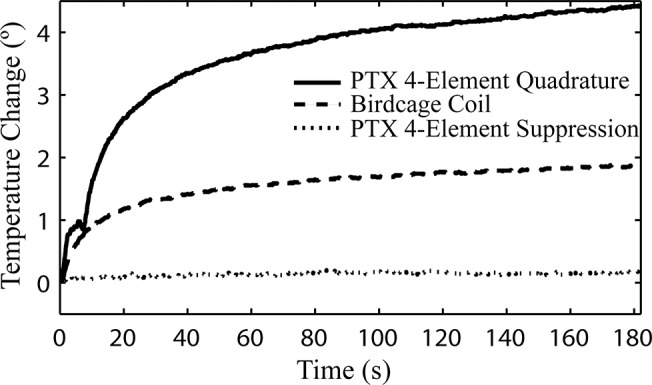
Deep Brain Stimulation (DBS) is increasingly used to treat a variety of brain diseases by sending electrical impulses to deep brain nuclei through long, electrically conductive leads. Magnetic resonance imaging (MRI) of patients pre- and post-implantation is desirable to target and position the implant, to evaluate possible side-effects and to examine DBS patients who have other health conditions. Although MRI is the preferred modality for pre-operative planning, MRI post-implantation is limited due to the risk of high local power deposition, and therefore tissue heating, at the tip of the lead. The localized power deposition arises from currents induced in the leads caused by coupling with the radiofrequency (RF) transmission field during imaging. In the present work, parallel RF transmission (pTx) is used to tailor the RF electric field to suppress coupling effects. Electromagnetic simulations were performed for three pTx coil configurations with 2, 4, and 8-elements, respectively. Optimal input voltages to minimize coupling, while maintaining RF magnetic field homogeneity, were determined for all configurations using a Nelder-Mead optimization algorithm. Resulting electric and magnetic fields were compared to that of a 16-rung birdcage coil. Experimental validation was performed with a custom-built 4-element pTx coil. In simulation, 95-99% reduction of the electric field at the tip of the lead was observed between the various pTx coil configurations and the birdcage coil. Maximal reduction in E-field was obtained with the 8-element pTx coil. Magnetic field homogeneity was comparable to the birdcage coil for the 4- and 8-element pTx configurations. In experiment, a temperature increase of 2±0.15°C was observed at the tip of the wire using the birdcage coil, whereas negligible increase (0.2±0.15°C) was observed with the optimized pTx system. Although further research is required, these initial results suggest that the concept of optimizing pTx to reduce DBS heating effects holds considerable promise.
Conflict of interest statement
Figures
Similar articles
-
Numerical Simulations of Realistic Lead Trajectories and an Experimental Verification Support the Efficacy of Parallel Radiofrequency Transmission to Reduce Heating of Deep Brain Stimulation Implants during MRI.Sci Rep. 2019 Feb 14;9(1):2124. doi: 10.1038/s41598-018-38099-w. Sci Rep. 2019. PMID: 30765724 Free PMC article.
-
Optimized radiofrequency shimming using low-heating B1+-mapping in the presence of deep brain stimulation implants: Proof of concept.PLoS One. 2024 Dec 18;19(12):e0316002. doi: 10.1371/journal.pone.0316002. eCollection 2024. PLoS One. 2024. PMID: 39693369 Free PMC article.
-
Parallel radiofrequency transmission at 3 tesla to improve safety in bilateral implanted wires in a heterogeneous model.Magn Reson Med. 2017 Dec;78(6):2406-2415. doi: 10.1002/mrm.26622. Epub 2017 Feb 28. Magn Reson Med. 2017. PMID: 28244142
-
Ultra-high field MRI: parallel-transmit arrays and RF pulse design.Phys Med Biol. 2023 Jan 18;68(2). doi: 10.1088/1361-6560/aca4b7. Phys Med Biol. 2023. PMID: 36410046 Review.
-
Magnetic resonance imaging conditionally safe neurostimulation leads: investigation of the maximum safe lead tip temperature.Neurosurgery. 2014 Feb;74(2):215-24; discussion 224-5. doi: 10.1227/NEU.0000000000000242. Neurosurgery. 2014. PMID: 24176957 Review.
Cited by
-
RF heating of deep brain stimulation implants during MRI in 1.2 T vertical scanners versus 1.5 T horizontal systems: A simulation study with realistic lead configurations.Annu Int Conf IEEE Eng Med Biol Soc. 2020 Jul;2020:6143-6146. doi: 10.1109/EMBC44109.2020.9175737. Annu Int Conf IEEE Eng Med Biol Soc. 2020. PMID: 33019373 Free PMC article.
-
Reconfigurable MRI technology for low-SAR imaging of deep brain stimulation at 3T: Application in bilateral leads, fully-implanted systems, and surgically modified lead trajectories.Neuroimage. 2019 Oct 1;199:18-29. doi: 10.1016/j.neuroimage.2019.05.015. Epub 2019 May 13. Neuroimage. 2019. PMID: 31096058 Free PMC article.
-
A single setup approach for the MRI-based measurement and validation of the transfer function of elongated medical implants.Magn Reson Med. 2021 Nov;86(5):2751-2765. doi: 10.1002/mrm.28840. Epub 2021 May 25. Magn Reson Med. 2021. PMID: 34036617 Free PMC article.
-
Numerical Simulations of Realistic Lead Trajectories and an Experimental Verification Support the Efficacy of Parallel Radiofrequency Transmission to Reduce Heating of Deep Brain Stimulation Implants during MRI.Sci Rep. 2019 Feb 14;9(1):2124. doi: 10.1038/s41598-018-38099-w. Sci Rep. 2019. PMID: 30765724 Free PMC article.
-
Optimized radiofrequency shimming using low-heating B1+-mapping in the presence of deep brain stimulation implants: Proof of concept.PLoS One. 2024 Dec 18;19(12):e0316002. doi: 10.1371/journal.pone.0316002. eCollection 2024. PLoS One. 2024. PMID: 39693369 Free PMC article.
References
-
- Bain PG. Deep Brain Stimulation. Oxford; New York: Oxford University Press; 2009.
-
- Grill WM. Safety considerations for deep brain stimulation: review and analysis. Expert Review of Medical Devices. 2005;2(4):409–20. - PubMed
Publication types
MeSH terms
LinkOut - more resources
Full Text Sources
Other Literature Sources
Medical
