. 2015 Jan 1;50(1):214-229.
doi: 10.1109/JSSC.2014.2355822.

A Fully-Implantable Cochlear Implant SoC with Piezoelectric Middle-Ear Sensor and Arbitrary Waveform Neural Stimulation

Affiliations

A Fully-Implantable Cochlear Implant SoC with Piezoelectric Middle-Ear Sensor and Arbitrary Waveform Neural Stimulation

Marcus Yip et al. IEEE J Solid-State Circuits. .

Abstract

A system-on-chip for an invisible, fully-implantable cochlear implant is presented. Implantable acoustic sensing is achieved by interfacing the SoC to a piezoelectric sensor that detects the sound-induced motion of the middle ear. Measurements from human cadaveric ears demonstrate that the sensor can detect sounds between 40 and 90 dB SPL over the speech bandwidth. A highly-reconfigurable digital sound processor enables system power scalability by reconfiguring the number of channels, and provides programmable features to enable a patient-specific fit. A mixed-signal arbitrary waveform neural stimulator enables energy-optimal stimulation pulses to be delivered to the auditory nerve. The energy-optimal waveform is validated with in-vivo measurements from four human subjects which show a 15% to 35% energy saving over the conventional rectangular waveform. Prototyped in a 0.18 μm high-voltage CMOS technology, the SoC in 8-channel mode consumes 572 μW of power including stimulation. The SoC integrates implantable acoustic sensing, sound processing, and neural stimulation on one chip to minimize the implant size, and proof-of-concept is demonstrated with measurements from a human cadaver ear.

Keywords: Arbitrary waveform; SoC; cochlear implant; energy-efficient; hearing loss; implantable; low-voltage; microphone; middle ear; piezoelectric; reconfigurable; stimulation; ultra-low-power.


Figures

Fig. 1
Fig. 1
Block diagram of a conventional cochlear implant.
Fig. 2
Fig. 2
Block diagram of the fully-implantable cochlear implant SoC.
Fig. 3
Fig. 3
(a) Block diagram and (b) photograph of the measurement setup and discrete prototype used to characterize the piezoelectric sensor mounted on the middle ear of a human cadaveric temporal bone.
Fig. 4
Fig. 4
(a) Umbo velocity and (b) charge amplifier output voltage versus ear canal sound pressure at 0.5, 1, 2, and 4.7 kHz. (c) Spectrum of the charge amplifier output for sound pressure levels from 40 to 90 dB SPL.
Fig. 5
Fig. 5
(a) Equivalent circuit for the charge amplifier including noise sources, and (b) the corresponding block diagram.
Fig. 6
Fig. 6
Block diagram of the 0.6 V digital reconfigurable multi-rate CIS sound processor.
Fig. 7
Fig. 7
Structure of the reconfigurable FIR filter (Type 3) used for channels A, C, E, G that can be reconfigured into 3 modes: 14-, 16-, and 20-tap used in 4-, 6-, or 8-channel modes.
Fig. 8
Fig. 8
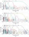
Effective frequency response of the multi-rate filter bank at 16 kHz reconfigured in (a) 4-channel, (b) 6-channel, and (c) 8-channel modes.
Fig. 9
Fig. 9
(a) Energy-optimal stimulation waveform at 25 μs/phase from the heuristic search using the computational nerve fiber model. Rectangular and exponential waveforms are included for comparison. (b) Perceived loudness versus energy delivered per phase from four human subjects.
Fig. 10
Fig. 10
(a) Schematic of the high-voltage electrode switch matrix during the cathodic phase of electrode 2. (b) Schematic of the fast-settling 6-bit current steering DAC.
Fig. 11
Fig. 11
Timing diagram for the digital control of the electrode switch matrix.
Fig. 12
Fig. 12
Ultra-low-voltage digital control of the stimulator. (a) Electrode selection state machine. (b) High-voltage electrode switch matrix control generation. (c) Digital arbitrary waveform interface.
Fig. 13
Fig. 13
Die micrograph of the prototype SoC.
Fig. 14
Fig. 14
Measured gain response of the charge amplifier (stage 1) of the PZFE with (a) CP = 3.2 nF and (b) CP = 0.56 nF. Panel (c) shows the combined response of the charge amplifier and PGA (stage 1 and 2). Simulation results are shown with dotted lines.
Fig. 15
Fig. 15
Measured spectrograms at the output of the (a) ADC, (b) 4-channel processor, (c) 6-channel processor, and (d) 8-channel processor when a logarithmic chirp signal is applied at the input. (e) Ideal Matlab simulation to compare against the measured results shown in (d).
Fig. 16
Fig. 16
Measured current and voltage of a model electrode (Rs = 3 kΩ, Cd = 10 nF) with (a) a rectangular waveform, and (b) the energy-optimal waveform. (c) Measured current pulse trains at 1,000 pulses/sec through all electrodes in 8-channel mode.
Fig. 17
Fig. 17
Measured total stimulator power across 8-, 6-, and 4-channel modes for phase widths of (a) 25 μs and (b) 50 μs.
Fig. 18
Fig. 18
(a) Spectrogram and time-domain waveform of the input speech signal (“her husband brought some flowers”) to the audio amplifier driving the speaker placed in the ear canal of the temporal bone. (b) Measured spectrogram and reconstructed sound from the SoC with the piezoelectric sensor mounted on a cadaver temporal bone.

References

    1. Young DJ, Zurcher MA, Semaan M, Megerian CA, Ko WH. MEMS capacitive accelerometer-based middle ear microphone. IEEE Trans Biomed Eng. 2012 Dec;59(12):3283–3292. - PubMed
    1. Germanovix W, Toumazou C. Design of a micropower current-mode log-domain analog cochlear implant. IEEE Trans Circuits Syst II. 2000 Oct;47(10):1023–1046.
    1. Sarpeshkar R, Baker MW, Salthouse CD, Sit JJ, Turicchia L, Zhak SM. An analog bionic ear processor with zero-crossing detection. IEEE Int. Solid-State Circuits Conf. Dig. Tech. Papers; San Francisco, CA. Feb. 2005; pp. 78–79.
    1. Whiten DM. PhD dissertation. Massachusetts Institute of Technology; Cambridge, MA: Feb, 2007. Electro-anatomical models of the cochlear implant.
    1. Wongsarnpigoon A, Grill WM. Energy-efficient waveform shapes for neural stimulation revealed with a genetic algorithm. J Neural Eng. 2010 Aug;7(4) - PMC - PubMed

LinkOut - more resources