. 2015 Oct;17(5):88.
doi: 10.1007/s10544-015-9993-2.

A multilayered microfluidic blood vessel-like structure

Affiliations

A multilayered microfluidic blood vessel-like structure

Anwarul Hasan et al. Biomed Microdevices. 2015 Oct.

Abstract

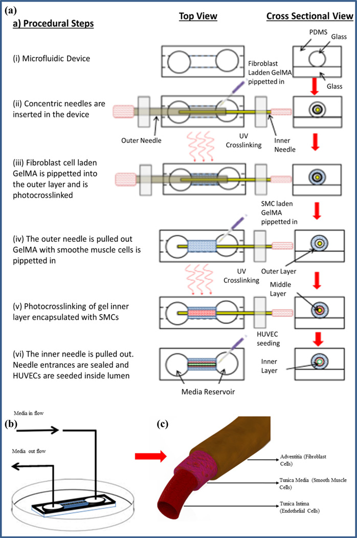
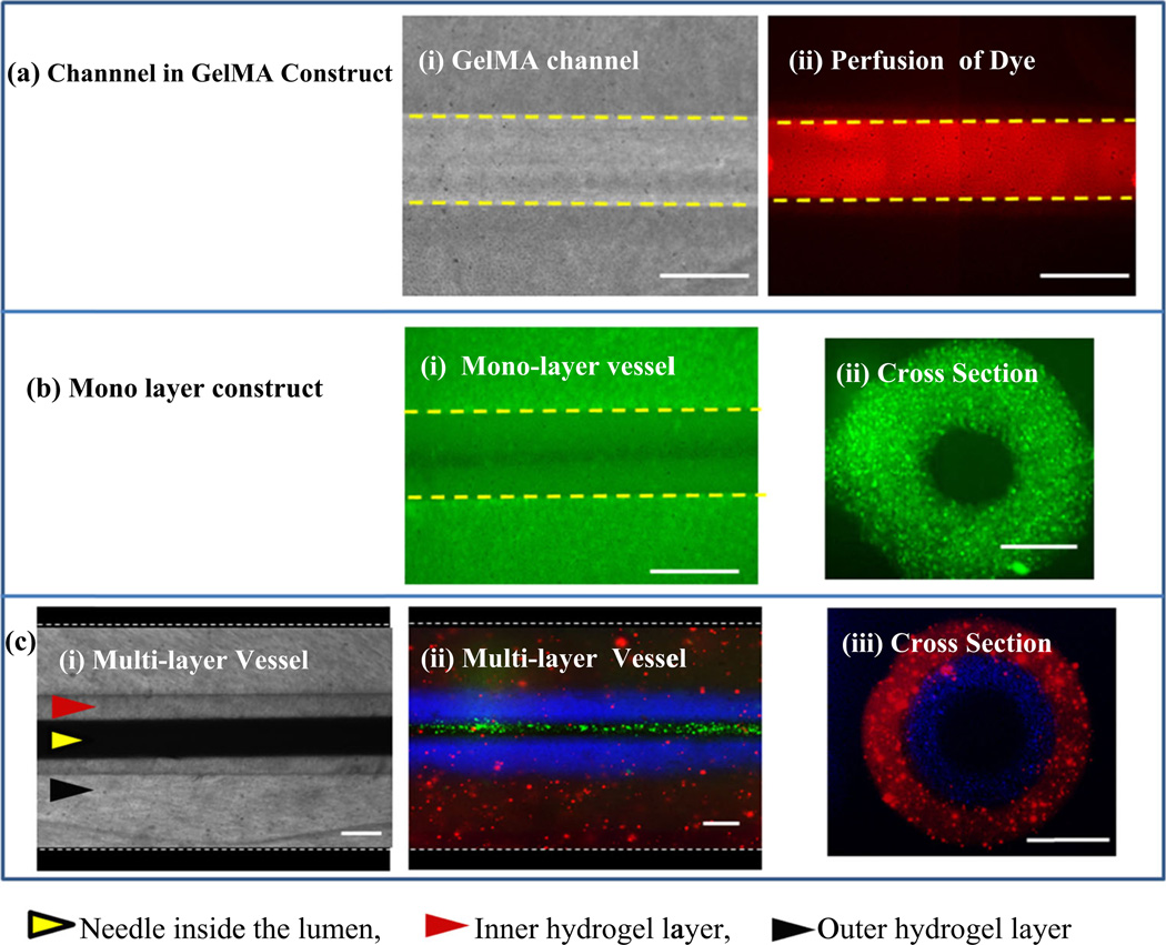
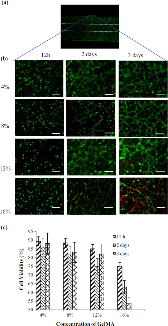
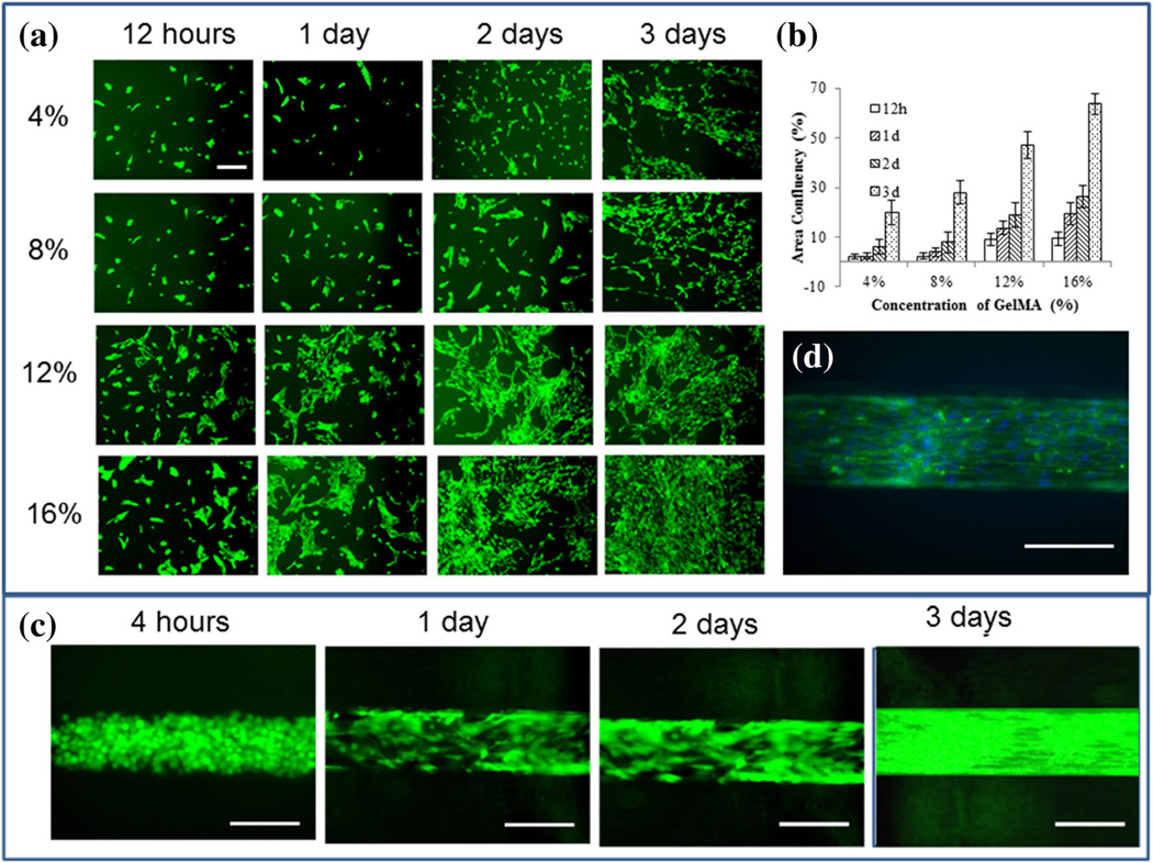
There is an immense need for tissue engineered blood vessels. However, current tissue engineering approaches still lack the ability to build native blood vessel-like perfusable structures with multi-layered vascular walls. This paper demonstrated a new method to fabricate tri-layer biomimetic blood vessel-like structures on a microfluidic platform using photocrosslinkable gelatin hydrogel. The presented method enables fabrication of physiological blood vessel-like structures with mono-, bi- or tri-layer vascular walls. The diameter of the vessels, the total thickness of the vessel wall and the thickness of each individual layer of the wall were independently controlled. The developed fabrication process is a simple and rapid method, allowing the physical fabrication of the vascular structure in minutes, and the formation of a vascular endothelial cell layer inside the vessels in 3-5 days. The fabricated vascular constructs can potentially be used in numerous applications including drug screening, development of in vitro models for cardiovascular diseases and/or cancer metastasis, and study of vascular biology and mechanobiology.


Figures

Fig. 1
Fig. 1
Schematic illustration of the step-by-step fabrication process of the tri-layer blood vessel-like structure in a microfluidic device, a (i) the middle layer of the three-layer PDMS device was fabricated by casting liquid PDMS on a silicon wafer mold prepared using microfabrication technique or as described in section 2.4. A glass capillary tube was affixed in the channel inside the middle part of the device which was plasma bonded to the bottom layer, a glass slide, (ii) two concentric needles were inserted in the device from opposite ends. The outer space was filled with fibroblast cell-laden GelMA, (iii) the gel outer layer encapsulated with fibroblast cells was photocrosslinked, (iv) The outer needle was pulled out leaving a concentric annular gap between inner needle and the outer gel layer. GelMA prepolymer solution laden with SMCs was pipetted into the concentric annular space. (v) The inner gel layer, GelMA laden with SMCs, was photocrosslinked. (vi) The inner needle was carefully pulled out leaving a bilayer cellular structure in the microfluidic device. Needle entrances were sealed, and HUVECs were seeded inside lumen resulting in a tri-layer vascular-like structure. b Perfusion of cell culture media through the fabricated structure in the microfluidic device was established, c the tri-layer vascular structure fabricated through the process
Fig. 2
Fig. 2
Illustration of the single and multilayer vascular-like structures, a a tubular Channel fabricated in bare GelMA: (i) phase contrast images of a 200 µm channel in bare GelMA, (ii) fluorescent image after flowing FITC through a 200 µm channel in GelMA; b a single layer vascular-like construct; (i) fluorescent image of top view of the vascular-like structure with green fluorescent beads encapsulated in the wall, (ii) cross-sectional side view of the structure showing the lumen and the wall of the construct; c a multilayer vascular-like structure: (i) top view bright field image of the bilayer structure, (ii) top view of the bilayer structure with fluorescent beads of different colors encapsulated in different layers, (iii) cross-sectional side view of the structure showing the lumen and the two layers of the wall. Scale bars = 200 µm
Fig. 3
Fig. 3
Viability of 3T3 fibroblast cells in the walls of the fabricated vascular structure of cell encapsulated GelMA at different concentrations over time. The cell-laden GelMA constructs were stained with Calcein-AM (green) and ethidium homodimer (red) at 12 h, 2 and 3 days after encapsulation, a a vascular construct showing the cells encapsulation in the vascular structure of GelMA, b live-dead staining of 4, 8, 12 and 16 % GelMA constructs after 12 h, 2 and 3 days, c cell viability at different time points in 4, 8, 12 and 16 % GelMA constructs after 12 h, 2 and 3 days. Cell viability in the low concentration GelMA constructs were considerably higher compared to high density GelMA. Scale bars = 100 µm
Fig. 4
Fig. 4
Formation of the EC monolayer on 2D GelMA surface and inside the lumen of the vascular-like structure, a GFP-fluorescent images showing attachment, spreading and growth of HUVECs on 2D GelMA surface at 4, 8, 12 and 16 % GelMA concentrations after 12 h, 1, 2 and 3 days of cell seeding, b area of confluence of HUVECs on 2D GelMA surface over time for different GelMA concentrations. c Spreading of HUVECs inside the lumen of a vascular-like structure with 12 % GelMA concentration over time, and d a representative Phalloidin-DAPI staining image showing the continuous monolayer of HUVECs in the channel at 12 % GelMA concentration after 3 days of cell seeding. The cells spread well on both the 2D surface and the luminal surface, forming a cell monolayer, as is seen from the actin skeleton (green) and the nucleus of the cells (blue). Scale bars in figures a are 100 µm while those in figures b and c are 200 µm
Fig. 5
Fig. 5
Permeability of fluorescently labeled 10 kDA dextran to the walls of. the vessel-like structures from the flow in the lumen: a a vessel without any EC layer at time zero of starting the dextran perfusion, b a vessel with an EC monolayer at time zero of starting perfusion, c a vessel without any EC layer after 20 min of dextran perfusion, d a vessel with an EC monolayer after 20 min of dextran perfusion. e and f Change in relative intensity of fluorescence with respect to the distance from the center of the vessels for the vascular-like structures without and with the EC monolayer respectively. The fluorescent intensity from line scannings across the vessels orthogonal to the axial direction at their center in a and b was measured at a time interval of 10 min. The intensities were then normalized against the maximum intensity values at the center of the vessel. g and h The relative intensity values at a distance 300 µm from the center of the vessels at different time points. The barrier function was obtained from the slope of the relative intensity versus time graphs in g and h. Scale bars = 200 µm

References

    1. Barthes J, Özçelik H, Hindié M, Ndreu-Halili A, Hasan A, Vrana NE. Cell microenvironment engineering and monitoring for tissue engineering and regenerative medicine: the recent advances. BioMed research international. 2014:18. - PMC - PubMed
    1. Benton JA, Deforest CA, Vivekanandan V, Anseth KS. Photocrosslinking of gelatin macromers to synthesize porous hydrogels that promote valvular interstitial cell function. Tissue Eng. Part A. 2009;15:3221–3230. - PMC - PubMed
    1. Browning MB, Dempsey D, Guiza V, Becerra S, Rivera J, Russell B, Höök M, Clubb F, Miller M, Fossum T, Dong JF, Bergeron AL, Hahn M, Cosgriff-Hernandez E. Multilayer vascular grafts based on collagen-mimetic proteins. Acta Biomater. 2012;8:1010–1021. - PubMed
    1. Cao L, Arany PR, Wang YS, Mooney DJ. Promoting angiogenesis via manipulation of VEGF responsiveness with notch signaling. Biomaterials. 2009;30:4085–4093. - PMC - PubMed
    1. Chen RR, Silva EA, Yuen WW, Brock AA, Fischbach C, Lin AS, Guldberg RE, Mooney DJ. Integrated approach to designing growth factor delivery systems. Faseb J. 2007;21:3896–3903. - PubMed

Publication types