Review
. 2013 Sep 25;1(3):216-48.
doi: 10.4248/BR201303002. eCollection 2013 Sep.

Bone Regeneration Based on Tissue Engineering Conceptions - A 21st Century Perspective

Affiliations
Review

Bone Regeneration Based on Tissue Engineering Conceptions - A 21st Century Perspective

Jan Henkel et al. Bone Res. .

Abstract

The role of Bone Tissue Engineering in the field of Regenerative Medicine has been the topic of substantial research over the past two decades. Technological advances have improved orthopaedic implants and surgical techniques for bone reconstruction. However, improvements in surgical techniques to reconstruct bone have been limited by the paucity of autologous materials available and donor site morbidity. Recent advances in the development of biomaterials have provided attractive alternatives to bone grafting expanding the surgical options for restoring the form and function of injured bone. Specifically, novel bioactive (second generation) biomaterials have been developed that are characterised by controlled action and reaction to the host tissue environment, whilst exhibiting controlled chemical breakdown and resorption with an ultimate replacement by regenerating tissue. Future generations of biomaterials (third generation) are designed to be not only osteoconductive but also osteoinductive, i.e. to stimulate regeneration of host tissues by combining tissue engineering and in situ tissue regeneration methods with a focus on novel applications. These techniques will lead to novel possibilities for tissue regeneration and repair. At present, tissue engineered constructs that may find future use as bone grafts for complex skeletal defects, whether from post-traumatic, degenerative, neoplastic or congenital/developmental "origin" require osseous reconstruction to ensure structural and functional integrity. Engineering functional bone using combinations of cells, scaffolds and bioactive factors is a promising strategy and a particular feature for future development in the area of hybrid materials which are able to exhibit suitable biomimetic and mechanical properties. This review will discuss the state of the art in this field and what we can expect from future generations of bone regeneration concepts.

Keywords: additve manufacturing; bone tissue engineering; clinical translation; regenerative medicine; scaffolds.


Figures

Figure 1
Figure 1
Hierarchical structural organization of bone: (A) cortical and cancellous bone; (B) osteons with Haversian systems; (C) lamellae; (D) collagen fibre assemblies of collagen fibrils; (E) bone mineral crystals, collagen molecules, and non-collagenous proteins. Reproduced with permission from (3), ©1998 IPEM.
Figure 2
Figure 2
Clinical case combining the Masquelet-technique and the RIA-system to treat a tibial non-union. 51 year old male acquired a Gustillo 3B fracture of the right tibia and fibula and was treated with a stage procedure with locked plating and a free flap. The patient's progress was very slow and an implant failure occurred 8 months post-operatively (A). The patient was then referred for the further management and underwent debridement of the non-union site on the distal tibia by lifting the flap (B). The size of the extensive bone defect is shown in B (intraoperative image of situs and X-ray image with retractor in defect site). Additionally, a PMMA bone cement spacer was inserted into the tibial defect as part of the Masquelet technique. Postop X-ray images after surgery with the PMMA spacer (circles) in place (C). 8 weeks later the PMMA spacer was removed and the induced membrane at the defect site was packed with autologous cancellous bone graft obtained from the femur using the Reamer-Irrigator-Aspirator (RIA) technique. (D) shows assembled RIA system, insert showing morselised autologous bone and bone marrow graft obtained. Postop films after the second surgery (E). 7 weeks after bone grafting the defect showed good healing and patient was able to fully bear weight as tolerated. Over the following 2 months X-ray images showed progressive bridging of the zone and he was able to return to work with light duties. He was reviewed again 7 months post-surgery and had returned to work full-time and was walking long distances without any support (F).
Figure 3
Figure 3
Schematic illustrating the interdependence of molecular weight loss and mass loss of a slow-degrading composite scaffold plotted against time, which corresponds with tissue regeneration. Scaffold, as shown by SEM (A) is implanted at t = 0 (B) with lower figures (C-E) showing a conceptual illustration of the biological processes of bone formation over time. The scaffold is immediate filled with a hematoma on implantation (C) followed by vascularization (D) and gradually new bone is formed within the scaffold (E). As the scaffold degrades over time there is increased bone remodeling within the implant site until eventually the scaffold pores are entirely filled with functional bone and vascularity. SEM of scaffold degraded over time (G) with associated schematic visualization of how mPCL-TCP scaffolds degrade via long-term bioerosion process, which takes up to 36 months in vivo (h). Reproduced with permission from (80), © Elsevier Ltd 2012.
Figure 4
Figure 4
For tissue engineering, the Valley of Death is the gap and associated funding difficulties of taking tissue engineering technologies to tissue-engineered products. The Valley exists due to the need of obtaining funding to develop scalable/GMP design and manufacturing processes, the need for pre-clinical studies proving therapies in large animal models, and finally, the need to progress to clinical trials. Reproduced with permission from (184), © 2009 IOP Publishing Ltd.
Figure 5
Figure 5
Bone tissue engineering strategies rely on three-dimensional scaffolds that constitute an inductive/conductive extracellular microenvironment for stem cell function as well as a delivery vehicle and 3D scaffold of clinically relevant properties and proportions. In fulfilling these dual criteria the biomimetic scaffold plays a critical role bridging the gap between the developmental context of stem cell mediated tissue formation and the adult context of injury and disease. Reproduced with permission from (187), © 2008 Elsevier Inc.
Figure 6
Figure 6
Load-bearing critical-sized ovine tibial defect model using mPCL-TCP scaffolds manufactured by FDM. Scaffolds (A=clinical image, holes are oriented towards neurovascular bundle to further promote ingrowth of vasculature) exhibit mechanical and structural properties comparable to cancellous bone and can be produced with distinct control over scaffold properties (porosity, pore size, interconnections etc.) by AM. B= Side and top view of a mPCL-TCP scaffold visualised by microcomputed tomography. The fabrication via FDM enables well-controlled architecture as evidenced by the narrow filament thickness distribution, leading to a porosity (volume fraction available for tissue ingrowth) of 60%, with interconnected pores. Scale bars are 5 mm. [Image B reproduced with permission from (246), © The Authors.] C-H = Surgical procedure: A 6cm tibial defects is created in the tibial diaphysis (C-D) and the periosteum is removed from the defect site and additionally also from 1cm of the adjacent bone proximally and distally. Special care is taken not to damage the adjacent neurovascular bundle (E, bundle indicated by Asterisk). The defect site is then stabilised using a 12 hole DCP (Synthes) (F). Afterwards 6cm mPCL-TCP scaffold loaded with PRP and rhBMP-7 is press fitted into the defect site to bridge the defect (G-H) and the plate is fixed in its final position. Xray analysis at 3 months after implantation (I) shows complete bridging of the defect site with newly formed radio-opaque mineralised tissue (in order to provide sufficient mechanical support, the scaffold is not fully degraded yet and scaffold struts appear as void inside the newly formed bone tissue).
Figure 7
Figure 7
The use of mPCL-CaP scaffolds for spinal fusion. (1) (A) Micro-computed tomography (m-CT) image of a biodegradable mPCL-TCP scaffold. (B) Representative scanning electron microscopy image at 100×magnification. (2) Image of scaffold prior to implantation. (3) Pictorial series demonstrating the implantation process of a PCL-based scaffold: (A) Cleared intervertebral disc space prepared for implantation. (B) Implantation process of scaffold into prepared intervertebral disc space. Scaffold being inserted into prepared intervertebral space. (C) Scaffold in situ within a predefined intervertebral disc space. (D) Internal fixation with a 5.5mm titanium rod and two vertebral screws stabilize the treatment level. (4) Representative reconstructed parasagittal CT images at 6 months demonstrating radiologically evident high fusion levels of (A) the recombinant human bone morphogenetic protein-2 (rhBMP-2) plus calcium phosphate (CaP)-coated PCLbased scaffold and (B) autograft groups, while lower fusion levels were seen in the (C) CaP-coated PCL-based scaffold alone group. (5) Representative histological (longitudinal) sections of specimen at 6 months post surgery from PCL-based scaffold plus rhBMP-2 group exhibiting well aligned columns of mineralized bone (indicated by letters “col”) seen interdigitating with struts of the scaffold filaments (indicated by letters “SC”). Reproduced with permission from (233), © Mary Ann Liebert, Inc.
Figure 8
Figure 8
Clinical case showing the craniofacial scaffold applications for orbital floor fractures. Moldable scaffolds (A−D) are used and mechanical stability, early vascularisation, osteoconductivity and ease of handling have been well balanced in the design of mPCL scaffold sheets in order to properly meet the clinician's needs. The clinical follow up 2.5 years postsurgery (lower CT image) of a patient receiving a mPCL scaffold (defect site shown in upper CT image) for the reconstruction of a orbital floor fracture defect showed complete bone regeneration of the defect site (arrow). Reproduced ith permission from (92), © 2007 John Wiley and Sons.
Figure 9
Figure 9
Clinical case of a 52 year old man with a malignant bone tumour above his left hip. (A) X ray and computed tomogram showing mixed lytic sclerotic lesion above the left acetabulum, Technitium-MDP bone scan demonstrating focal area of increased tracer uptake within the tumour. (B) Tumour resection leaving a large pelvic defect (white arrows), f=femoral head. (C) Resected specimen including upper part of acetabulum (Clinical images: P.F.C.). The surgical resection creates a large bone defect in the pelvis that necessitates the use of autograft/allograft bone material and/or orthopaedic implants to reconstitute the pelvic anatomy. A novel approach (D-G) could be the use of custom made porous bone tissue engineering scaffolds fabricated via Computer Aided Design (CAD) to regenerate such defects: Data obtained from high-resolution CT can be used to create a 3D computer-aided designed (CAD) model of the patient's pelvis by additive manufacturing (D). This model can be used by the orthopaedic surgeon to indicate osteotomy planes to achieve tumour free margins, after which, after which the CAD model is virtually resected (E). A custom made scaffold to fit the defined defect is then created by mirroring the healthy side of the pelvis, adjusting the size of the scaffold accordingly and fabricating the scaffold from the virtual model using AM techniques (F). Flanges, intramedullary pegs and other details can be added to the porous scaffold structure to facilitate surgical fixation and to enhance its primary stability after implantation (G). Images D-G reproduced with permission from (246), © The authors
Figure 10
Figure 10
The vascularised fibula transfer is one of the most commonly used techniques for reconstruction of large tibial defects in orthopaedic oncology. The figure shows clinical case from a 16 year old girl with a malignant tumour of the mid-shaft of tibia. A: Xray showing destructive lesion. B: Segmental resection of tumour. C: Defect created by the removal of tumour. D: Example of reconstruction using vascularised fibular within allograft bone (Cappanna procedure). E: Reconstruction in-situ using vascularised fibular and allograft. F: postoperative X-ray images. G: 3D computed tomogram of reconstruction showing fibula enclosed by allograft bone material (Clinical case: P.F.C.). A novel biological approach to avoid the use of allograft material could be the combination of a vascularised fibula transfer with a custom made tissue engingeering construct as shown in H: After resection of the malignant tumour (1), a customized tubular scaffold is placed around the vascularised fibula autograft to fill the defect (2,3). Primary stability and even load distribution is achieved by using an internal fixation device (4). Secondary stability is achieved by osseointegration of both the fibula and the porous tissue engineering scaffold. Over time, the scaffold is slowly replaced by ingrowing tissue engineered bone and the defect is completely bridged and regenerated (5). H partly reproduced with permission from (246), © The Authors.

References

    1. Mason C. Regenerative medicine 2.0. Regen Med. 2007;2:11–18. - PubMed
    1. Webster TJ, Ahn ES. Nanostructured biomaterials for tissue engineering bone. Adv Biochem Eng Biotechnol. 2007;103:275–308. - PubMed
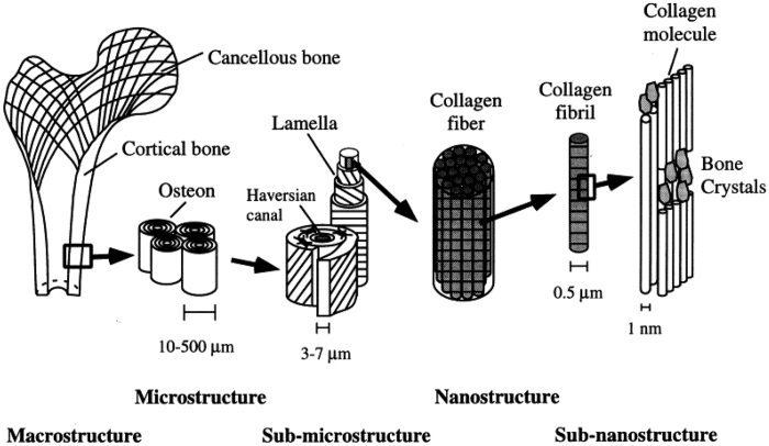
    1. Rho JY, Kuhn-Spearing L, Zioupos P. Mechanical properties and the hierarchical structure of bone. Med Eng Phys. 1998;20:92–102. - PubMed
    1. Keaveny TM, Morgan EF, Niebur GL, Yeh OC. Biomechanics of trabecular bone. Annu Rev Biomed Eng. 2001;3:307–333. - PubMed
    1. Barrère F, Mahmood TA, De Groot K, van Blitterswijk CA. Advanced biomaterials for skeletal tissue regeneration: Instructive and smart functions. Mat Sci Eng R. 2008;59:38–71.