. 2015 Jul 17;6(8):2934-45.
doi: 10.1364/BOE.6.002934. eCollection 2015 Aug 1.

Characterizing microstructures of cancerous tissues using multispectral transformed Mueller matrix polarization parameters

Affiliations

Characterizing microstructures of cancerous tissues using multispectral transformed Mueller matrix polarization parameters

Chao He et al. Biomed Opt Express. .

Abstract

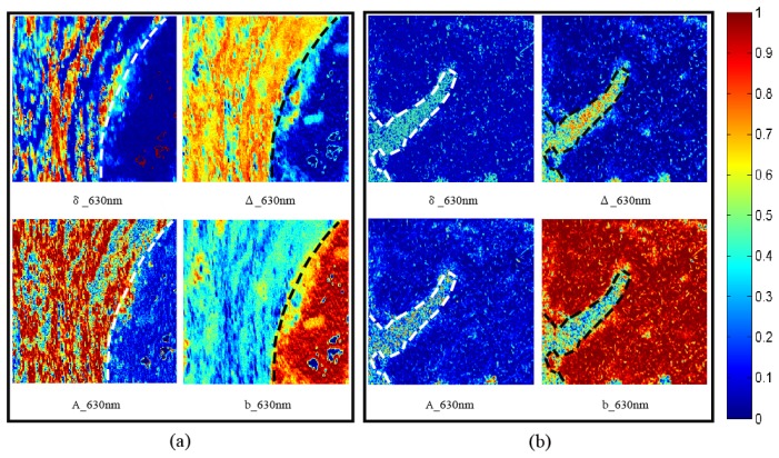
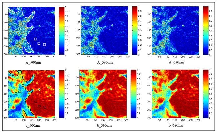
In this paper, we take the transmission 3 × 3 linear polarization Mueller matrix images of the unstained thin slices of human cervical and thyroid cancer tissues, and analyze their multispectral behavior using the Mueller matrix transformation (MMT) parameters. The experimental results show that for both cervical and thyroid cancerous tissues, the characteristic features of multispectral transmitted MMT parameters can be used to distinguish the normal and abnormal areas. Moreover, Monte Carlo simulations based on the sphere-cylinder birefringence model (SCBM) provide additional information of the relations between the characteristic spectral features of the MMT parameters and the microstructures of the tissues. Comparisons between the experimental and simulated data confirm that the contrast mechanism of the transmission MMT imaging for cancer detection is the breaking down of birefringent normal tissues for cervical cancer, or the formation of birefringent surrounding structures accompanying the inflammatory reaction for thyroid cancer. It is also testified that, the characteristic spectral features of polarization imaging techniques can provide more detailed microstructural information of tissues for diagnosis applications.

Keywords: (110.5405) Polarimetric imaging; (170.3880) Medical and biological imaging; (290.5855) Scattering, polarization.


Figures

Fig. 1
Fig. 1
Schematic of the forward MMT experimental setup. L1, L2: lens; VariSpec: liquid crystal transmission filter; R: quarter wave plate; P1, P2: polarizer; The light source (halogen lamp) is about 40 cm away from the sample. The diameter of the illumination area is about 1.5 cm. The field of view and magnification of the imaging system are 0.5 cm × 0.5 cm and 0.4, respectively.
Fig. 2
Fig. 2
(a), (b) Photograph of the 28 μm thick slices of unstained human cervix and papillary thyroid carcinoma tissues, the red squares indicate the imaging regions and the black squares indicate the testing regions used for Fig. 3, (c), (d) microscopic images of the corresponding H-E stained slices of cancerous and healthy cervical tissues, (e), (f) microscopic images of the corresponding H-E stained slices of cancerous and healthy thyroid tissues.
Fig. 3
Fig. 3
Pseudo-color images of the MMPD and MMT parameters of (a) cervical carcinoma tissue and (b) papillary thyroid carcinoma tissue. The wavelength of incident light is 630 nm. The cancerous and healthy regions of the tissues are distinguished by the white and black dotted lines.
Fig. 4
Fig. 4
Pseudo-color images of the MMT parameter A (upper row) and parameter b (lower row) for the unstained human cervix carcinoma tissue slice with the incident wavelengths of 500 nm, 590 nm, 680 nm. The imaging region is indicated by the red square in Fig. 2(a). The white and black dotted lines represent the border of the cancerous tissue and the healthy tissue approximately, and the squares represent the random sample areas used for quantitative analysis.
Fig. 5
Fig. 5
Values of parameter A (a) and b (b) of the normal and cancerous cervical tissues at different wavelengths.
Fig. 6
Fig. 6
Pseudo-color images of the MMT parameter A (upper row) and parameter b (lower row) for the unstained slice of human papillary thyroid carcinoma tissue with the incident wavelengths of 500 nm, 590 nm, 680 nm. The imaging region is indicated by the red square in Fig. 2(b). The white and black dotted lines represent the border of the cancerous tissue and the healthy tissue approximately, and the squares represent the random sample areas used for quantitative analysis.
Fig. 7
Fig. 7
Values of parameter A (a) and b (b) of the normal and human papillary thyroid carcinoma tissues at different wavelengths.
Fig. 8
Fig. 8
Multispectral Monte Carlo simulation results of the parameters A (a) and b (b) using the sphere-birefringence model with 0.001, 0.002 and 0.003 birefringence Δn values.
Fig. 9
Fig. 9
Monte Carlo simulation results of: (a), (b) Values of parameter A and b of the sphere-cylinder scattering model. The diameters and the scattering coefficients of the cylindrical scatterers are set to be 1.5 μm and 200 cm−1, 0.2 μm and 200 cm−1, 0.2 μm and 400 cm−1, respectively. The parameters of the spherical scatterers remain the same as Fig. 8. (c), (d) Values of parameter A and b of the sphere-birefringence model. The diameter of the small spherical scatterers is set to be 0.2 μm, 0.5 μm, and 0.8 μm. The other parameters are the same as Fig. 8. (e), (f) Values of parameter A and b of the sphere-birefringence model. The ratio between the scattering coefficients of the small and large spheres is changed from 50:150 to 100:100 and 150:50.

References

    1. Gurjar R. S., Backman V., Perelman L. T., Georgakoudi I., Badizadegan K., Itzkan I., Dasari R. R., Feld M. S., “Imaging human epithelial properties with polarized light-scattering spectroscopy,” Nat. Med. 7(11), 1245–1248 (2001).10.1038/nm1101-1245 - DOI - PubMed
    1. Kunnen B., Macdonald C., Doronin A., Jacques S., Eccles M., Meglinski I., “Application of circularly polarized light for non-invasive diagnosis of cancerous tissues and turbid tissue-like scattering media,” J. Biophotonics 8(4), 317–323 (2015).10.1002/jbio.201400104 - DOI - PubMed
    1. Ghosh N., Vitkin I. A., “Tissue polarimetry: concepts, challenges, applications, and outlook,” J. Biomed. Opt. 16(11), 110801 (2011).10.1117/1.3652896 - DOI - PubMed
    1. Alali S., Vitkin A., “Polarized light imaging in biomedicine: emerging Mueller matrix methodologies for bulk tissue assessment,” J. Biomed. Opt. 20(6), 061104 (2015).10.1117/1.JBO.20.6.061104 - DOI - PubMed
    1. Jacques S. L., Roman J. R., Lee K., “Imaging superficial tissues with polarized light,” Lasers Surg. Med. 26(2), 119–129 (2000).10.1002/(SICI)1096-9101(2000)26:2<119::AID-LSM3>3.0.CO;2-Y - DOI - PubMed

LinkOut - more resources