. 2015 Sep 1;109(5):883-91.
doi: 10.1016/j.bpj.2015.07.013.

Quantitative Analysis of Intracellular Fluorescent Foci in Live Bacteria

Affiliations

Quantitative Analysis of Intracellular Fluorescent Foci in Live Bacteria

M Charl Moolman et al. Biophys J. .

Abstract

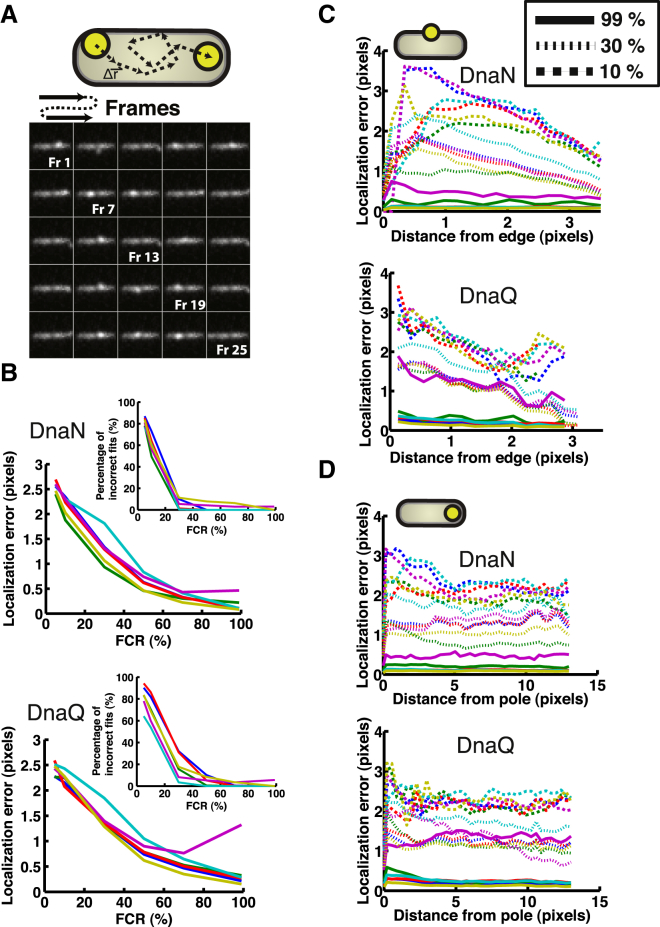
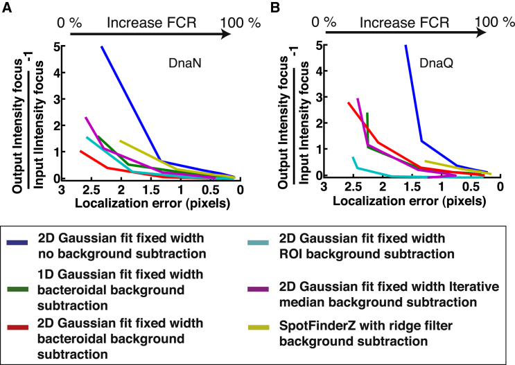
Fluorescence microscopy has revolutionized in vivo cellular biology. Through the specific labeling of a protein of interest with a fluorescent protein, one is able to study movement and colocalization, and even count individual proteins in a live cell. Different algorithms exist to quantify the total intensity and position of a fluorescent focus. Although these algorithms have been rigorously studied for in vitro conditions, which are greatly different than the in-homogenous and variable cellular environments, their exact limits and applicability in the context of a live cell have not been thoroughly and systematically evaluated. In this study, we quantitatively characterize the influence of different background subtraction algorithms on several focus analysis algorithms. We use, to our knowledge, a novel approach to assess the sensitivity of the focus analysis algorithms to background removal, in which simulated and experimental data are combined to maintain full control over the sensitivity of a focus within a realistic background of cellular fluorescence. We demonstrate that the choice of algorithm and the corresponding error are dependent on both the brightness of the focus, and the cellular context. Expectedly, focus intensity estimation and localization accuracy suffer in all algorithms at low focus to background ratios, with the bacteroidal background subtraction in combination with the median excess algorithm, and the region of interest background subtraction in combination with a two-dimensional Gaussian fit algorithm, performing the best. We furthermore show that the choice of background subtraction algorithm is dependent on the expression level of the protein under investigation, and that the localization error is dependent on the distance of a focus from the bacterial edge and pole. Our results establish a set of guidelines for what signals can be analyzed to give a targeted spatial and intensity accuracy within a bacterial cell.


Figures

Figure 1
Figure 1
Studying a fluorescent focus in the inhomogeneous background of a bacterial cell. (A) Sample fluorescence signal of a focus and cellular background as measured in a single E. coli cell. Here the dashed blue line indicates where the line profile in (A) was taken. (B) The corresponding line profile of the sample image in (A). Here we indicate the focus and the cellular background to illustrate the nonnegligibility of the background signal when analyzing foci in this context. Scale bar: 1 μm. To see this figure in color, go online.
Figure 2
Figure 2
Separation of focus and background signals. (A) General workflow used to assess background removal methods and their effect on focus analyses. First, the focus and background signals are split using one of the methods described in Materials and Methods. The resulting focus signal is processed by the different focus analysis methods as described in Materials and Methods. The result is assessed in terms of estimating the focus signal content and focus position. (B) A sample result of subtracting the background using our bacteroidal background subtraction algorithm. (Top) The line profile of the original image (inset). (Middle) The line profile of the bacteroidal background generated (inset) using the steps described in Materials and Methods. (Bottom) The result of subtracting the date in the middle panel from the date in the top panel. One can appreciate that the background has been substantially reduced. In all the images the dashed blue line indicates where the line profile was taken. Scale bars: 1 μm. To see this figure in color, go online.
Figure 3
Figure 3
The approach taken to systematically evaluate the different algorithms of analyzing a focus. (A) Illustration of our approach of increasing the amount of signal in a focus, while simultaneously maintaining a constant total fluorescence value in the cell. For each increment we simulate a diffraction limited focus with more fluorescence content (red line), while also subtracting that amount of fluorescence from the cellular signal (blue line). We schematically illustrate the effect on the focus and cytoplasmic signal. (B) A sample temporal montage of a complete simulation from no signal in a focus (far left side of A) until the signal consists only of a focus (far right side of A). (C) Three sample simulations of different focus fluorescence content together with their corresponding line profile plots. Scale bars: 1 μm. Note that the cellular background is measured and not simulated. To see this figure in color, go online.
Figure 4
Figure 4
Comparison of the different algorithms for determining the total intensity of a focus. (A and B) The ratio of the signal in the focus (as estimated utilizing the different algorithms) versus the known total cellular signal plotted for the two different strains DnaN (A) and DnaQ (B), respectively. Here we plot the percentage of the estimated focus content divided by the known total signal. (Inset) The resulting error in terms of the difference between the focus content from the fit and the known focus content divided by the known focus content, plotted as function of FCR. We only show the fitted results up and until 100%. n = 42 cells for both (A) and (B). To see this figure in color, go online.
Figure 5
Figure 5
Comparison of the performance of different background subtraction and focus analysis algorithms in localizing a focus. (A) An example montage of a simulated focus positioned at random positions in the cell. The cartoon illustrations the approach. Note that the focus appears less bright in Fr 2 compared with, for example, Fr 1. This is because of the background signal of the cell, and emphasizes the relevance of this work. (B) The error in localization of a focus utilizing the different background subtraction and analysis algorithms for the (top) DnaN and (bottom) DnaQ scenarios, respectively. Here the error is taken as 2× SD (95% confidence internal) of the distribution of the values resulting by subtracting the fit from the input value for each of the cells at a specific ratio value. (Inset) The percentage of incorrect fit positions for the different algorithms. An incorrect fit is defined here as a fit position that differs by >2 pixels from the input value. Only FCRs at 5%, 10%, 30%, 50%, 70%, and 99% were simulated because of the time-consuming nature of these simulations (n = 42 cells). The color code used is the same as used in Fig. 4. (C) Assessing the dependency of the localization error on the position of a focus from the cell edge for (top) DnaN and (bottom) DnaQ. Here we depict the error in localization for three different FCRs, namely 10% (dashed), 30% (striped), and 99% (solid). (D) Assessing the dependency of the localization error on the position of a focus from the cell pole: (top) DnaN and (bottom) DnaQ. Here we depict the error in localization for three different FCRs, namely 10% (dashed), 30% (striped), and 99% (solid). To see this figure in color, go online.
Figure 6
Figure 6
Summary of localization versus total intensity error. A comparison of the position and intensity errors for different FCR, namely 5%, 10%, 30%, 50%, 70%, and 99%. For (A), we combine Figs. 4A and 5B, top. For (B), we combine Figs. 4B and 5B, bottom. The results are shown for all the different algorithms. To see this figure in color, go online.

Similar articles

Cited by

References

    1. Xie X.S., Choi P.J., Lia G. Single-molecule approach to molecular biology in living bacterial cells. Annu. Rev. Biophys. 2008;37:417–444. - PubMed
    1. Darzacq X., Yao J., Singer R.H. Imaging transcription in living cells. Annu. Rev. Biophys. 2009;38:173–196. - PMC - PubMed
    1. Wu B., Piatkevich K.D., Verkhusha V.V. Modern fluorescent proteins and imaging technologies to study gene expression, nuclear localization, and dynamics. Curr. Opin. Cell Biol. 2011;23:310–317. - PMC - PubMed
    1. Biteen J.S., Moerner W.E. Single-molecule and superresolution imaging in live bacteria cells. Cold Spring Harb. Perspect. Biol. 2010;2:a000448. - PMC - PubMed
    1. Tuson H.H., Biteen J.S. Unveiling the inner workings of live bacteria using super-resolution microscopy. Anal. Chem. 2015;87:42–63. - PubMed

Publication types

MeSH terms

LinkOut - more resources