

Review
doi: 10.1021/acs.chemrev.5b00146.
Epub 2015 Sep 8.
Artificial Molecular Machines
Affiliations
- PMID: 26346838
- PMCID: PMC4585175
- DOI: 10.1021/acs.chemrev.5b00146
Item in Clipboard
Review
Artificial Molecular Machines
Chem Rev.
.
No abstract available
Figures
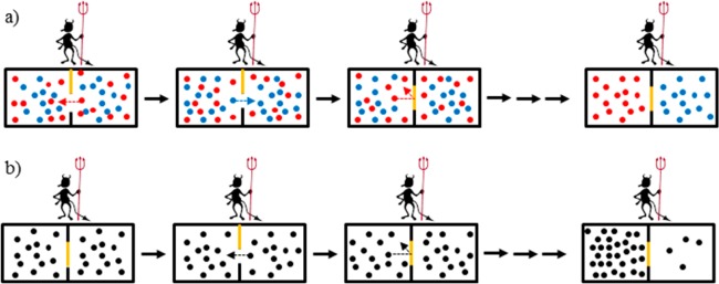
Maxwell’s
demons. (a) A “temperature demon”
sorts particles according to velocity, generating a temperature gradient.
(b) A “pressure demon” sorts particles according to
their direction of movement, generating a pressure gradient.

(a) In Smoluchowski’s
Trapdoor, a spring-loaded gate separates
the two sections of a container. The lack of energy dissipation leads
to a longer duration of opening and thus a uniform particle distribution
between the sections. (b) Feynman’s
ratchet-and-pawl device. The asymmetry of the teeth of the ratchet
cog was intended to drive directional movement. However, when T1 = T2, the rotation
is nondirectional.
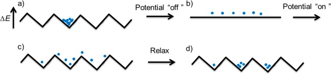
An on–off ratchet:
(a) the particles are located in an energy
minima, (b) the potential is turned off so that diffusion can occur
for a short time, and (c) the potential is turned on again. As the
potential is asymmetric, particles have a greater probability of being
trapped in an adjacent well to the right of the original one than
to the left. (d) Relaxation into the local energy minima leads to
the average position of the particles moving to the right.
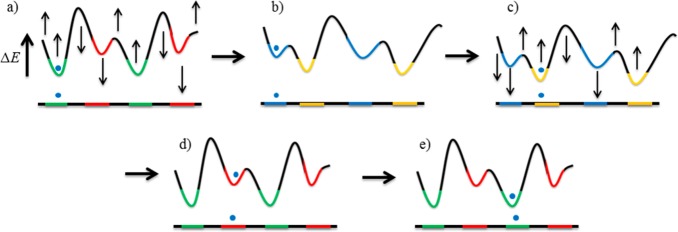
A flashing ratchet. In (a) and (c), the particle starts in a green
or orange well, respectively. Raising this energy minima while lowering
the adjacent maxima and minima triggers movement by Brownian motion
(b) to (c) or (d) to (e). By continuously varying the relative heights
of the energy barriers and minima of the energy wells, the particle
can be directionally transported.
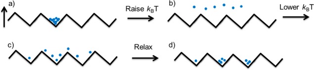
A temperature or diffusion
ratchet. (a) The particles are located
in an energy minima on the potential-energy surface, with energy barriers
≫kBT1. (b) The temperature is increased so that the height of the barriers
is ≪kBT2, and free diffusion is allowed to occur for a short time. (c) As
the temperature is lowered again, the asymmetric potential energy
surface means that the particles have a greater probability of being
trapped to the right of their initial position. (d) Relaxation to
the local energy minima.
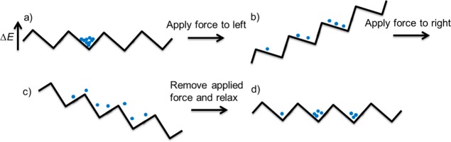
A rocking ratchet. (a) Particles are located in an energy minima
on the potential energy surface. (b) A directional force is applied
to the left. (c) An equal and opposite directional force is applied
to the right. (d) Removal of the force and relaxation to an energy
minima leads to the average position of the particles moving to the
right.
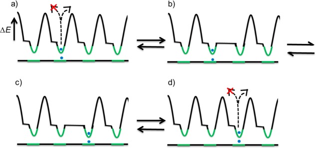
An information ratchet. In (a) and (d) the dotted lines represent
the transfer of information about the position of the particle. (b)
The position of the particle lowers the energy barrier to movement
to the right-hand well but not the left. (c) The particle moves by
Brownian motion.
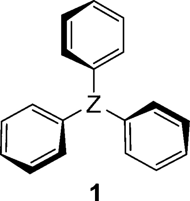
Chemical
structure of a triaryl molecule as an example of a molecular
propeller.,
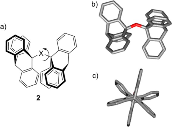
(a)
Molecular bevel gear 2, consisting of two 9-triptycyl
groups joined through a bridge head carbon to a central atom. (b) X-ray structure of the molecular bevel
gear (side view). (c) X-ray structure of the molecular bevel gear
(top view). Adapted with permission from ref (156). Copyright 1984 American
Chemical Society.
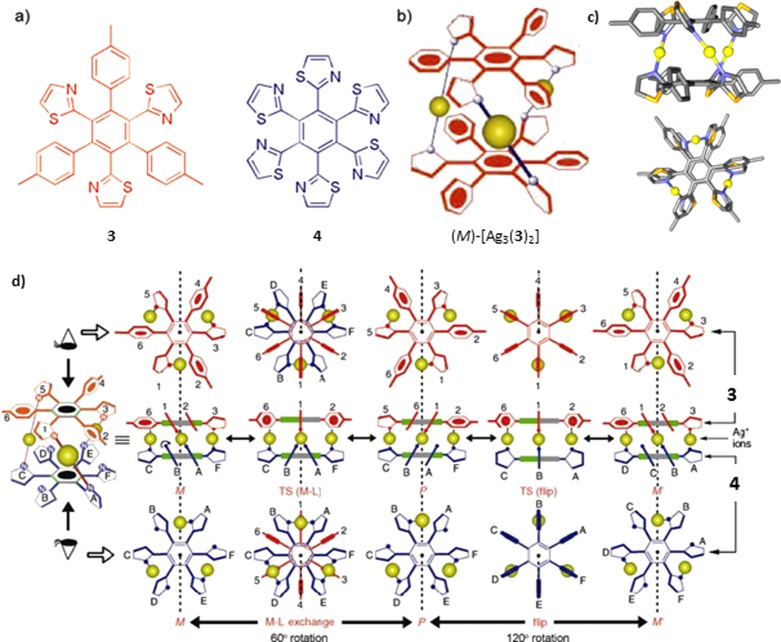
(a) Chemical structure of tris-monodentate
disk shaped ligand 3 and hexakis-monodentate ligand 4. (b) Schematic
representation of complex [Ag3(3)2] shown as its M-helical enantiomer. (c) X-ray structure
of complex [Ag3(3)2]. (d) Schematic representation of the flipping
motion of the rings attached to the disks and subsequent ligand exchange
from 1-A, 3-E, and 5-C in M to 1-B, 3-F, and 5-D
in P. The direction of rotation in the M to P transition is opposite to that of a subsequent P to M′ transition. Reprinted with permission from refs (197) and (200). Copyright 2003 and 2004
Wiley-VCH Verlag GmbH & Co. KGaA, Weinheim.
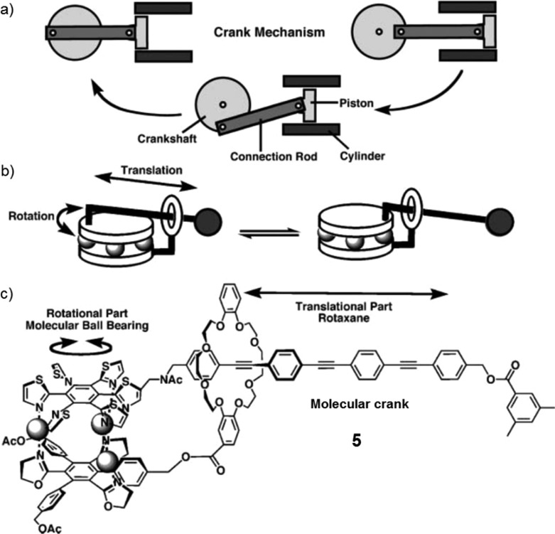
(a) Schematic illustration of a crank
mechanism that translates
linear motion into rotary motion in cylinder engines. (b) Schematic
representation of a molecular crank mechanism. (c) Chemical structure
of a synthetic molecular crank 5. Reprinted with permission from ref (201). Copyright 2010 Royal
Society of Chemistry.

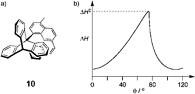
(a) Kelly’s ratchet-and-pawl 10. (b) Enthalpy
change on rotation of helicene. Reprinted with permission from ref (212). Copyright 1997 Wiley-VCH
Verlag GmbH & Co. KGaA, Weinheim.
Rotation is restricted in A and C by covalent
bonds, although helical inversion
is allowed, and in B and D by nonbonded
interactions, with directional control of rotation being provided
by stereospecific covalent bond cleavage.
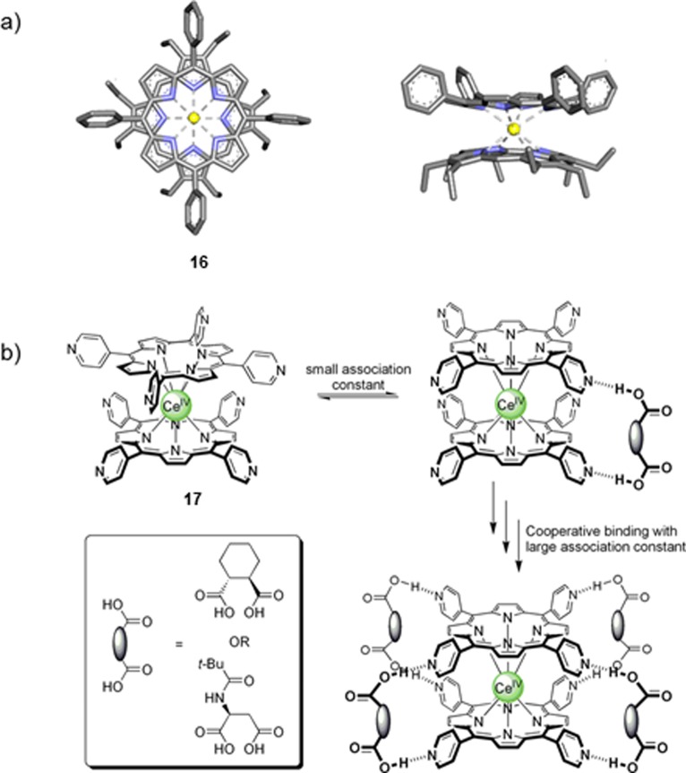
(a) X-ray
crystal structure of porphyrin double decker complex 16 with cerium(IV). Reprinted with permission from ref (228). Copyright 1989 Wiley-VCH
Verlag GmbH & Co. KGaA, Weinheim. (b) Representation of the cooperative
binding of guest molecules to porphyrin double decker complex 17.

Cerium(IV) bis(porphyrinate) double decker (top unit)
and a rhodium(III)
porphyrin-based side cog. The two units are connected through a coordination
bond between rhodium(III) and a pyridyl group.
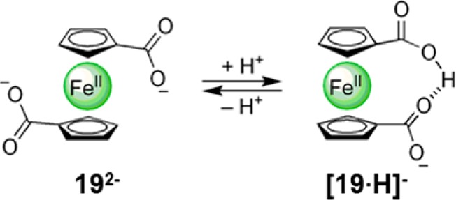
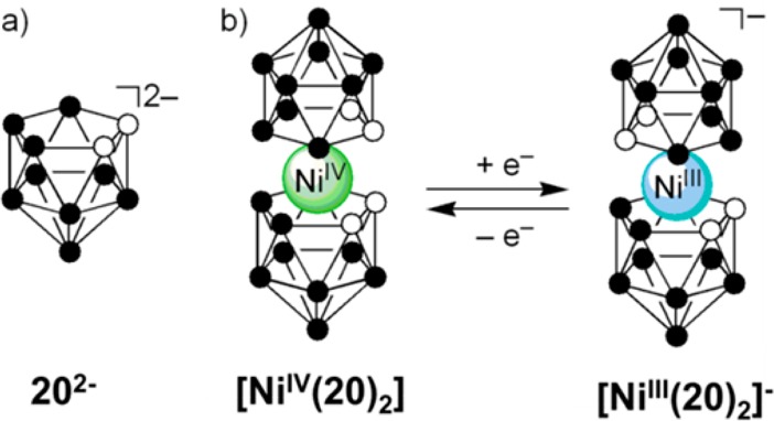
(a) Dicarbollide ligand 202–. (b)
Metallocarborane [Ni(20)2], an electrochemically
controlled rotary switch.
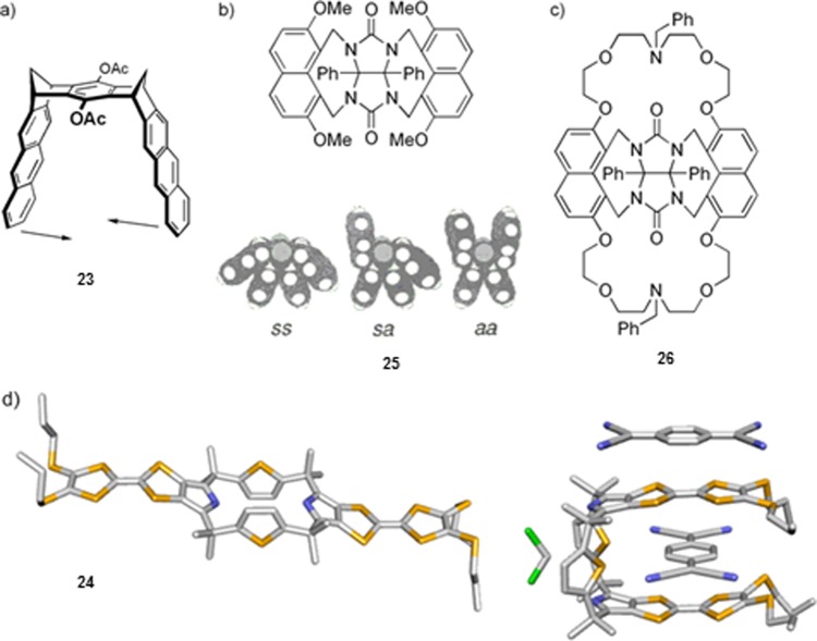
(a) Molecular tweezer 23, arrows indicate
direction
of contraction. (b) Clip 25, where the aa form is favored in the presence of a guest. (c) Clip 26, where ion binding enhances guest affinity. (d) Crystal structure
of uncomplexed and complexed 24.,,, X-ray crystal structure reprinted with permission from ref (282). Copyright 2007 American
Chemical Society.
Reprinted with permission
from ref (299). Copyright
2008 Wiley-VCH Verlag GmbH & Co. KGaA, Weinheim.

Reprinted with permission
from refs (321) and (327). Copyright 1997 and 2010
Wiley-VCH Verlag GmbH & Co. KGaA, Weinheim.
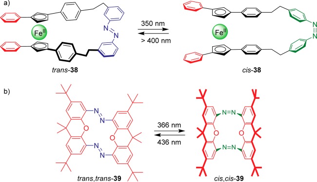
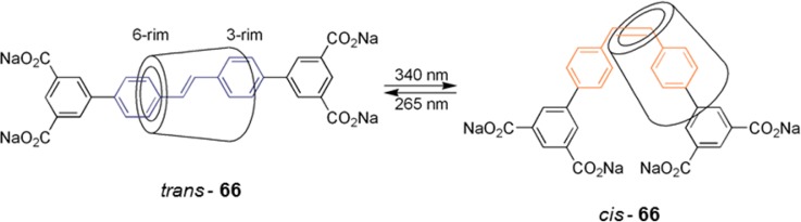
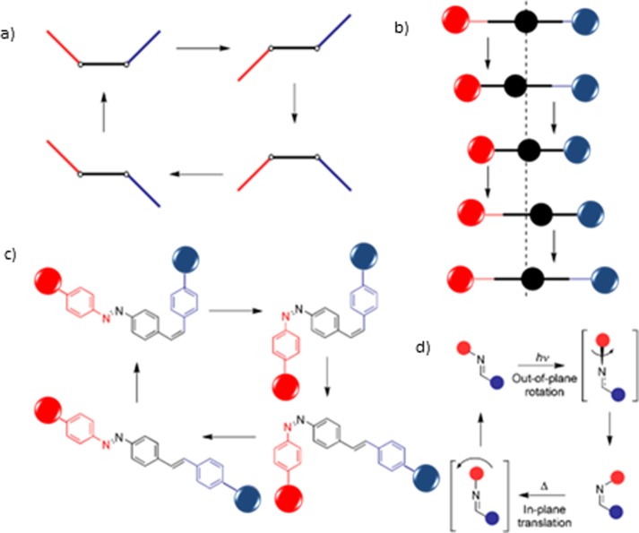
Irradiation at 350 nm initiates
photoisomerization from the trans to cis isomer of the azobenzene moiety (closed to open molecular scissor);
irradiation at >400 nm induces the reverse.

(a) Chemical structure of a molecular brake 40 with
a 2,5-dimethylbenzene unit as the rotor. (b) X-ray crystal structure.
(c) Schematic representation of this photoinduced molecular brake.
X-ray crystal structure reprinted with permission from ref (418). Copyright 2011 Wiley-VCH
Verlag GmbH & Co. KGaA, Weinheim.
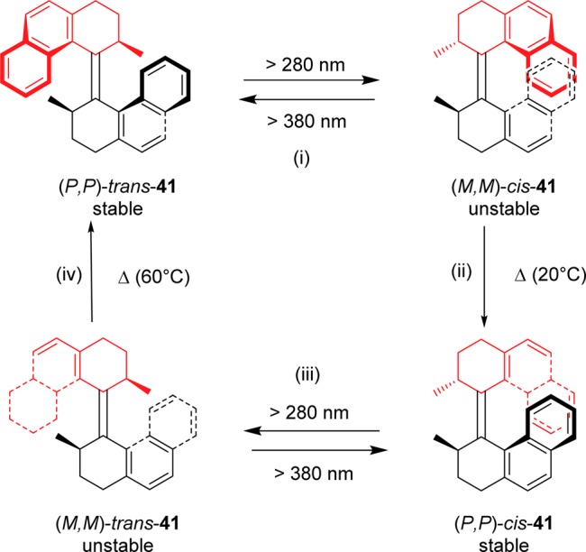
(i) Photochemical isomerization
leaves substituents in the unstable equatorial conformation (M,M)-(cis)-41-unstable. (ii) Steric strain is released by a thermally activated
helicity inversion leading to (P,P)-(cis)-41-stable. (iii) Photoisomerization
from cis to trans. (iv) Helical
inversion completes a full rotation.
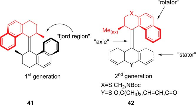
Comparison of the general structures for the first (41) and second (42) generations of Feringa’s molecular
motors.
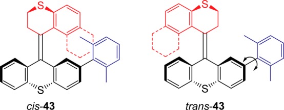
Structure of molecular brake 43.

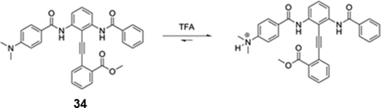
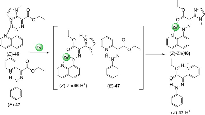
(a) Protonation of the pyridyl
nitrogen of compound (E)-44 induces E → Z isomerization. (b) The quinoline unit in (E)-45 provides a binding site for a Zn2+ ion,
which is now the trigger for E → Z isomerization.


Orthogonal exclusion of an azobenzene and a
viologen encapsulated
by CB[8].
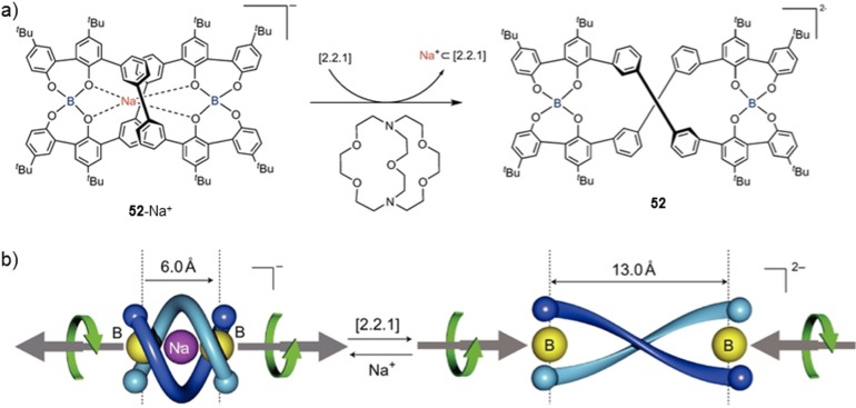
Na+-induced twisting in helicate 52. Reprinted
with permission from ref (589). Copyright 2010 Nature Publishing Group.
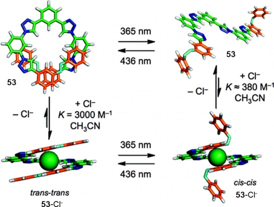
Control of
anion concentration in solution by a photoresponsive
foldamer. Reprinted with permission from ref (595). Copyright 2010 American
Chemical Society.


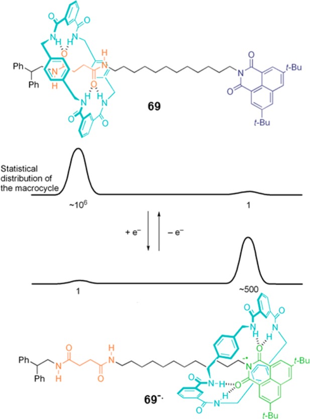
Idealized model of binding in degenerate molecular shuttles. Barrier
height is dependent on the energy required to break interactions between
macrocycle and station and a distance-dependent diffusional component.

Idealized
potential energy surface for macrocycle shuttling in
a degenerate, two-station molecular shuttle.
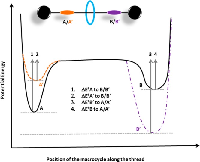
Potential energy diagram
of a rotaxane-based bistable molecular
shuttle.

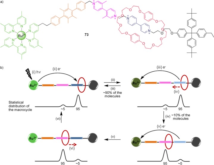
Photoinitiated redox-driven shuttling in a [2]-rotaxane
initiated
by (i) irradiation and (ii) subsequent reduction of viologen station.
(iii) Competing back electron transfer from one-electron reduced viologen
to Ru3+. (iv, v) With continuous irradiation the macrocycle
shuttles to the dimethylviologen station. (vi) Ceasing illumination
restores the macrocycle to its original position.
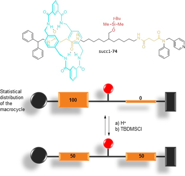
[2]Rotaxane 74 acts as an irreversible
mechanical
switch. The silyl ether is too bulky to allow macrocycle shuttling
between the two succinamide stations.
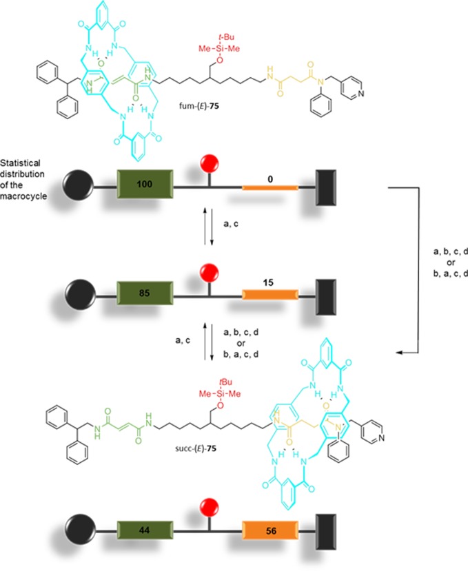
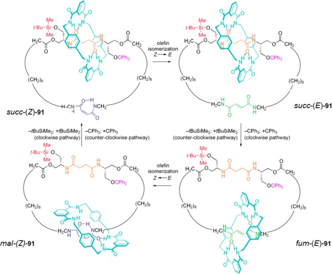
Operation of a compartmentalized molecular machine, which corresponds
to a two-state Brownian flip-flop. Operation steps: (a) Desilylation
(80% aqueous acetic acid); (b) E → Z photoisomerization (hν at 312 nm);
(c) resilylation (TBDMSCl); and (d) Z → E thermal isomerization (catalytic piperidine).
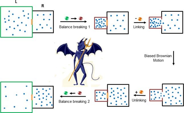
Initially the system is balanced (in proportion to the
sizes of
the two compartments), with an equal density of particles in the left
and the right compartments. By changing the volume of the left-hand
compartment, the system becomes statistically unbalanced. Opening
the door allows the particle to redistribute according to the new
size of the compartments. Closing the door ratchets the new distribution
of the particles. Restoring the left compartment to its original size
results in a concentration gradient of the Brownian particles across
the two compartments. Here, the size of the compartment represents
the energy level of the macrocycle-station system.
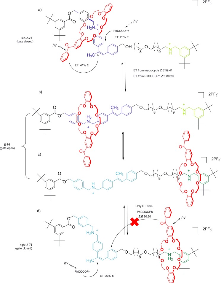
(a) Gate closed, but energy
transfer from the macrocycle is efficient. (b and c) Gate is open,
allowing free shuttling of the macrocycle. (d) The macrocycle is on
the green station, intramolecular energy transfer (ET) from the macrocycle
is inefficient; intermolecular energy transfer from PhCOCOPh dominates
(closing the gate).

Photodriven directional translational motion in pseudorotaxanes 86–87. Reprinted with permission from
ref (811). Copyright
2013 American Chemical Society.

Effect
of water on the rate of pirouetting of a macrocycle about
an axle. Reprinted with permission from ref (698). Copyright 2013 Nature
Publishing Group.

Directional
circumrotation in a [3]catenane. (i) hν (350
nm), (ii) hν (254 nm), (iii)
heating; or heating with catalytic ethylenediamine; or catalytic Br2, hν (400–670 nm). Adapted with
permission from ref (883). Copyright 2003 Nature Publishing Group.
Schematic representation
of an electric revolving door. (a) Door
closed-switch on leading to high conductance. (b) Door open-switch
off leading to low conductance.
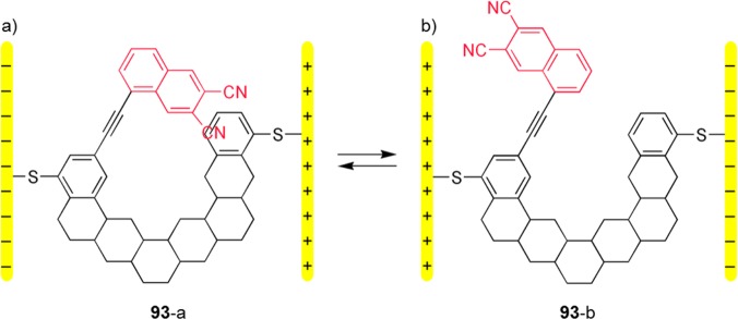
(a) High conductance predicted.
(b) Low conductance predicted.
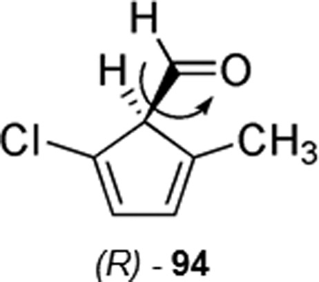
One enantiomer
of chiral molecule 94, in which directional
rotational motion was driven by linearly polarized laser pulses and
studied by quantum and classical mechanical simulations.
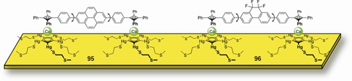
Nonpolar 95 and dipolar 96 altitudinal
rotors mounted on an Au(111) surface. Note that rotor and flanking
aryl rings are arbitrarily shown perpendicular to the surface for
clarity.
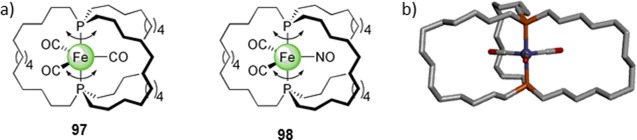
(a) Molecular structure of transition-metal-based gyroscopes 97 and 98. (b) X-ray structure of compound 97. X-ray crystal structure reprinted with permission from
ref (983). Copyright
2004 Wiley-VCH Verlag GmbH & Co. KGaA, Weinheim.
(a,b)
Proposed designs for swimmers viable at the nanoscale. (c,d)
Potential molecular solutions.
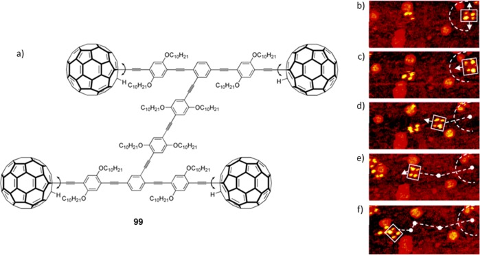
(a) Chemical structure
and (b–f) STM micrographs of translational
motion of a four-wheeled “nanocar” on an Au(111) surface
at 200 °C. Wheels are shown by yellow spots, and the path is
highlighted with a white arrow. Reprinted with permission from ref (1129). Copyright 2005 American
Chemical Society.
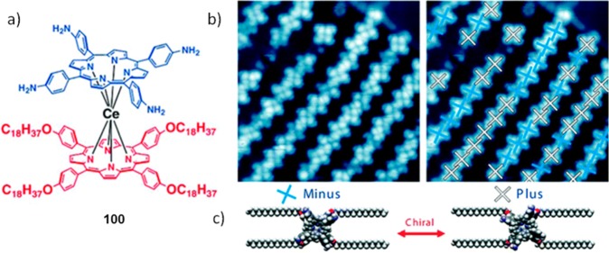
(a) Structure
of a cerium-centered double-decker molecule. (b)
STM micrographs of the molecules assembled on Au(111) surface. The
two distinct isomers, due rotational chirality, are shown in white
and blue crosses. (c) Space-filling model of the two chiral species.
Reprinted with permission from ref (1134). Copyright 2011 American Chemical Society.
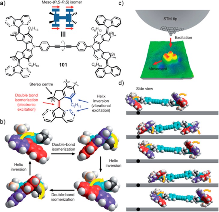
(a) Chemical structure of a rotary motor
with the groups responsible
for double-bond isomerization (red) and helix inversion (blue) highlighted.
(b) Schematic representation of a full 360° rotation with sequential
double-bond isomerization and helix inversion (hexyl substituents
are omitted for clarity). (c) Schematic representation of electron
tunneling exciting the molecule and inducing translational motion
on the surface. (d) Cartoon representation of the motion. Reprinted
with permission from ref (1135). Copyright 2011 Nature Publishing Group.
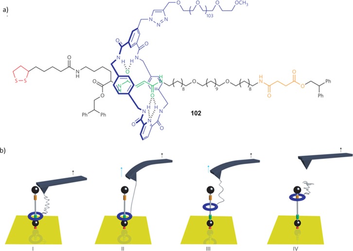
(a) Chemical structure of a rotaxane with fumaramide and
succinamide
stations depicted in green and orange, respectively. (b) Schematic
representation of macrocycle movement on a thread attached to a gold
surface as a result of the force exerted by an AFM probe. Application
of force by cantilever movement (I,II) was followed by repositioning
of the macrocycle (III) or detachment of the PEO tether (IV) depending
on the strength of the force. Reprinted with permission from ref (1143). Copyright 2011 Nature
Publishing Group.

Communication between
molecular devices. Acid generated upon conversion
of merocyanine (MEH+) to spiropyran (SP) protonates a pyridine,
and leads to subsequent complexation of the pyridinium ion (103+) by a calix[6]arene (104).
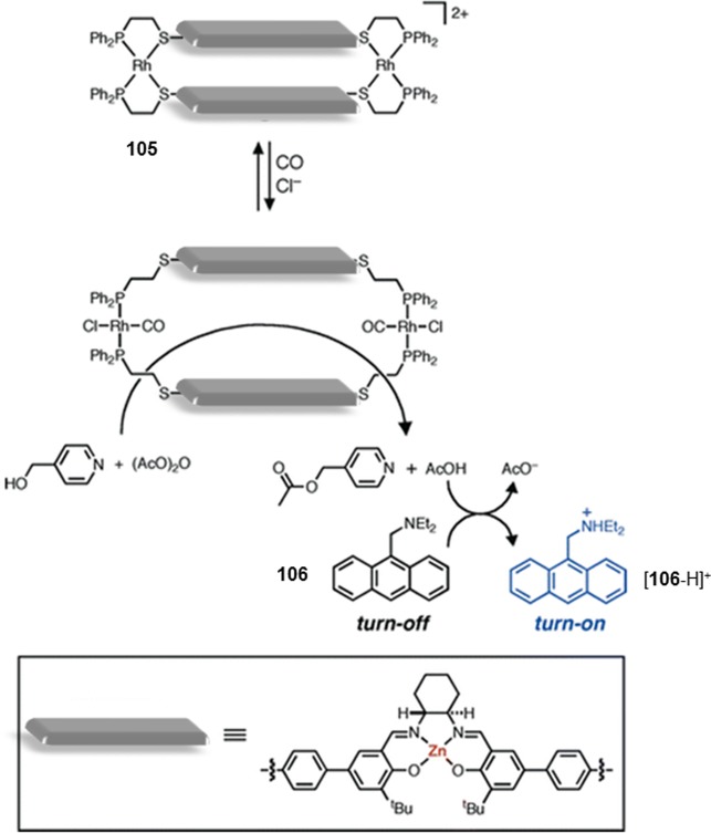
The Zn(II) center acts as
a catalytic unit, and diethylaminomethylanthracene is used as the
reporter.

(a) Chemical structure of the t-butylphenyl and
BODIPY-substituted foldamers, and (b) X-ray structure of the t-butylphenyl functionalized foldamer. Carbon atoms of the t-butyl groups and all hydrogen atoms except OH and NH have
been omitted for clarity. (c) Schematic representation of conformational
switching. D and A represent energy donor and acceptor modules, respectively.− Parts (a) and (c) are adapted with permission from ref (1268). Copyright 2007 Wiley-VCH
Verlag GmbH & Co. KGaA, Weinheim. Part (b) is reprinted with permission
from ref (1269). Copyright
2006 American Chemical Society.
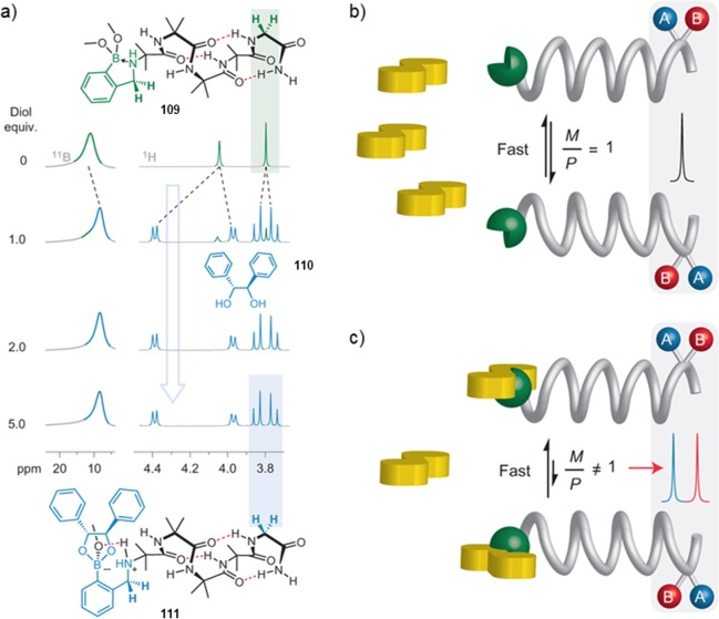
(a) Ligand-induced variation
of the chemical shifts (11B (160 MHz) and 1H
NMR (500 MHz)) of the helix in CD3OD at 298 K. (b) Schematic
representation of fast exchange
between two degenerate helical conformers with a single NMR signal
and (c) induced bias of helicity upon ligand binding (yellow), and
the anisochronous NMR signal generated. Adapted with permission from
ref (1298). Copyright
2013 Nature Publishing Group.
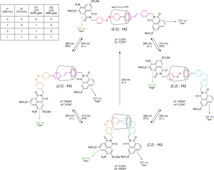
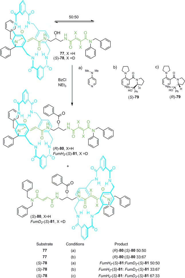
The percentage of the major
isomer in the photostationary state is shown over the reaction arrows.
The truth table for a half-adder logic gate is shown, with the inputs
being 380 nm (I1) and 313 nm (I2) irradiation, and outputs being the
change in absorbance (O2) and fluorescence (O1) values.
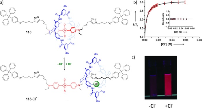
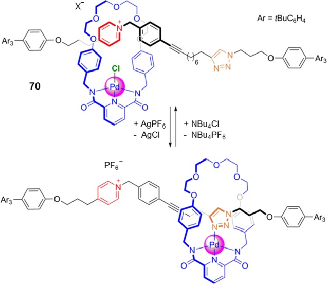
(a) Chloride-dependent shuttling of tetralactam
macrocycle, and
(b) subsequent fluorescence enhancement in CHCl3 upon titration
with tetrabutylammonium chloride. (c) Rotaxane solution in the absence
(left) or presence (right) of chloride. Adapted with permission from
ref (1310). Copyright
2010 Wiley-VCH Verlag GmbH & Co. KGaA, Weinheim.
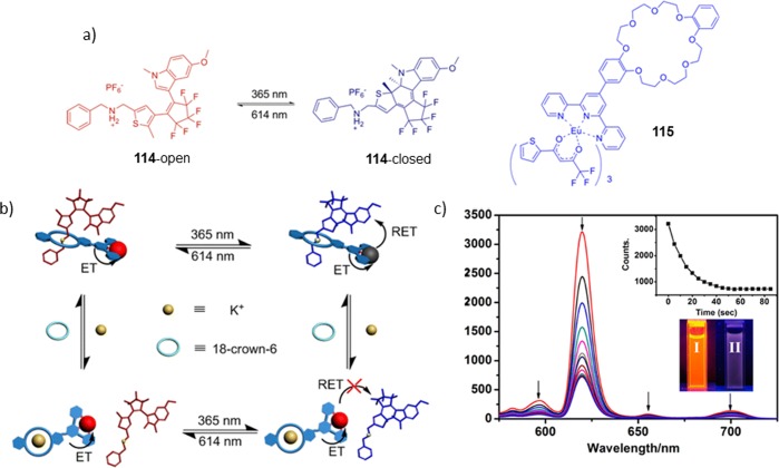
(a) Chemical structures of 115, and the open and closed
forms of 114. (b) Schematic representation of light modulated
switch and K+/18-crown-6-mediated complexation. (c) Fluorescence
quenching of the Eu3+ complex upon UV irradiation in 1:1
CH3CN/CHCl3. Fluorescence before (I) and after
(II) excitation at 390 nm (c inset). Reprinted with permission from
ref (1314). Copyright
2013 American Chemical Society.
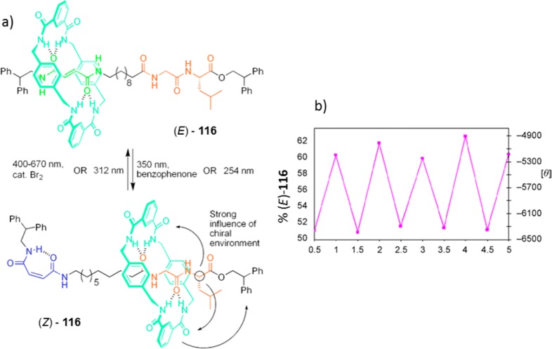
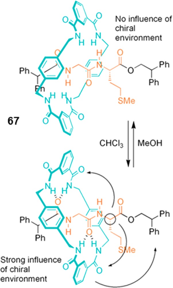
(a)
Chiraloptical switching upon photoinduced shuttling of the
macrocycle between fumaramide (green) and peptide (orange) stations;
the chiral center of the peptide station is highlighted by a black
circle. (b) Percentage of E isomer calculated using 1H NMR (left y axis) and induced CD absorption
at 246 nm after alternating irradiation between 254 nm (half integer)
and 312 nm (integers) (right y axis). Reprinted with
permission from ref (1326). Copyright 2003 American Chemical Society.
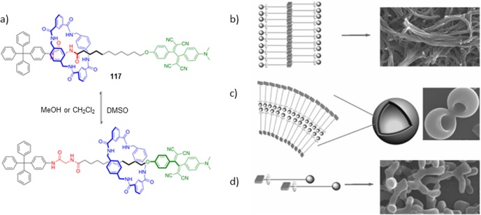
(a) Solvent-induced shuttling on a tetracyanobutadiene
bearing
rotaxane 117. (b) Proposed assembly of rotaxane and SEM
images in CHCl3/n-C6H14 (1/1, v/v), (c) in CHCl3/MeOH (1/1, v/v), and (d) in
DMSO. Reprinted with permission from ref (1327). Copyright 2009 Wiley-VCH Verlag GmbH &
Co. KGaA, Weinheim.


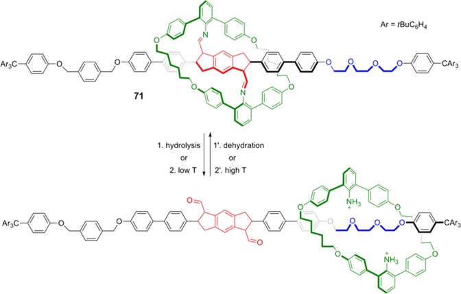
(a) The structure and operation of walker 125, which
uses dynamic imine exchange chemistry. Amine footholds are highlighted
in blue and red. Each molecule is labeled with one or two numbers
in parentheses indicating the amine footholds to which the walker
is attached (foothold amines are assigned with numbers starting from
the left). (b) 1H NMR spectra of indicated protons in CDCl3. H7 corresponds to a side product in which the
walker is detached from the track. Reprinted with permission from
ref (1395). Copyright
2012 American Chemical Society.
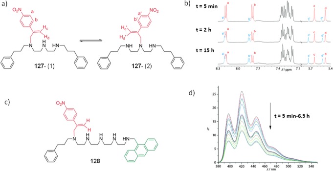
(a) The chemical structure of the model walker 127,
and (b) gradual change in 1H NMR of the model walker
in d6-DMSO upon formation of new positional
isomer on the track. Ratio of (1):(2) isomers reaches 1:0.9 after
15 h of operation. (c) Chemical structure of the walker on a larger
track bearing an anthracene moiety, 128. (d) Fluorescence
quenching of anthracene after 6.5 h of walking. Reprinted with permission
from ref (1397). Copyright
2012 Wiley-VCH Verlag GmbH & Co. KGaA, Weinheim.
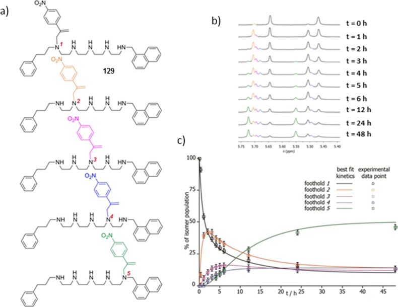
(a) Chemical structure of walker 129, with
each positional
isomer labeled in a different color, and amines numbered. (b) Change
in the partial 1H NMR spectra over 48 h of operation. (c)
Occupancy of each foothold over time. Reprinted with permission from
ref (1398). Copyright
2013 American Chemical Society.
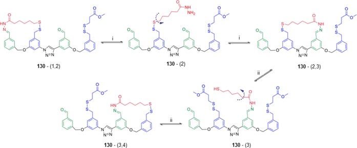
Footholds are shown
in blue
and green; the walker unit is depicted in red. Numbering shows the
footholds to which the walker is attached.

Toward directional molecular walkers. (a) Chemical structure and
schematic representation of the walker attached to the track, and
(b) operation of walking through successive acid–base addition
and heating cycles. Reprinted with permission from ref (1403). Copyright 2014 American
Chemical Society.
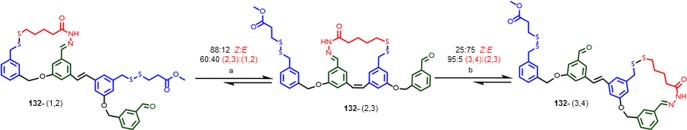
Footholds are shown in blue
and green; the walker unit is depicted in red. Each molecule is labeled
with two numbers in parentheses indicating the two footholds to which
the walker is attached. (a) (i) hν (365 nm),
CD2Cl2, (ii) DBU, DTT, CHCl3; (b)
(i) I2, hν (500 nm), CD2Cl2, (ii) TFA, CHCl3.

(a) Molecular structure of the photoswitchable piperidine base 133, and (b) X-ray structure of the photoswitchable piperidine
base 133. X-ray crystal structure reprinted with permission
from ref (1418). Copyright
2008 Wiley-VCH Verlag GmbH & Co. KGaA, Weinheim.
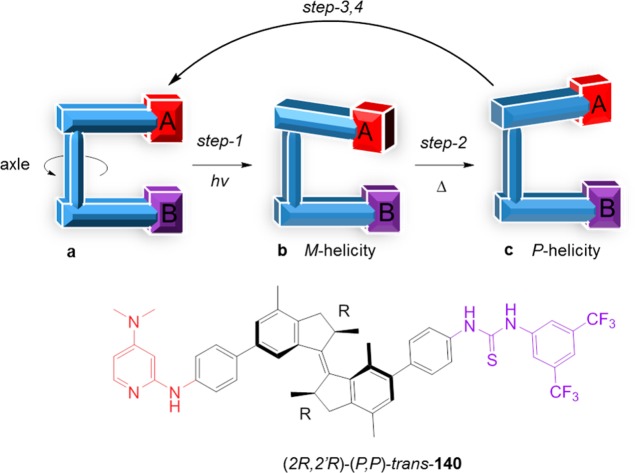
Schematic representation and molecular structure
of a bifunctional
organocatalyst integrated in a directional light-driven molecular
motor. A, DMAP; B, thiourea hydrogen-bonding donor group. (a) A and
B are remote. (b) A and B are in close proximity with M helicity in the (M,M)-cis-140 isomer, preferentially providing the
(S) enantiomer of the reaction product. (c) A and
B are in close proximity with P helicity in the (P,P)-cis-140 isomer, generating (R) enriched product. Step 1:
irradiation at 312 nm at 20 °C. Step 2: heating at 70 °C.
Step 3: irradiation at 312 nm at −60 °C. Step 4: temperature
−10 °C.
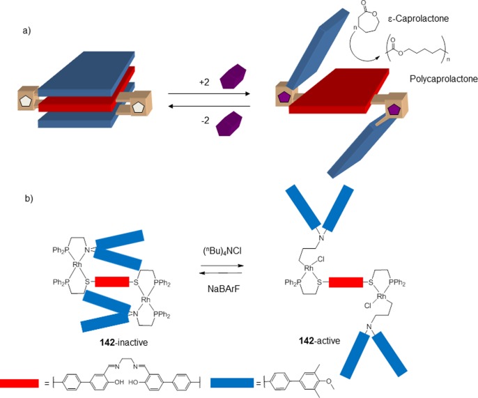
(a) Allosteric supramolecular triple-layer
complex 142, which regulates the catalytic living polymerization
of ε-caprolactone.
(b) Molecular structures of the components.

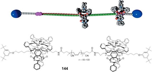
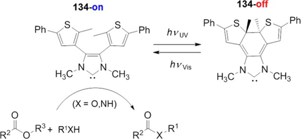
Porphyrin-catalyzed
epoxidation of a butadiene polymer by 144, utilizing
a rotaxane architecture. Reprinted with permission
from ref (1456). Copyright
2003 Nature Publishing Group.
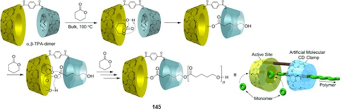
Reprinted with permission
from ref (1460). Copyright
2011 Wiley-VCH Verlag GmbH & Co. KGaA, Weinheim.
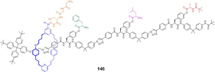
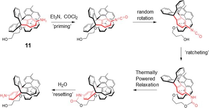
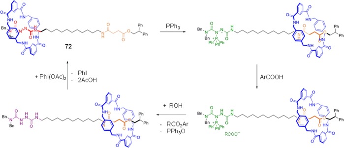
Leigh’s small molecule peptide synthesizer, 146.
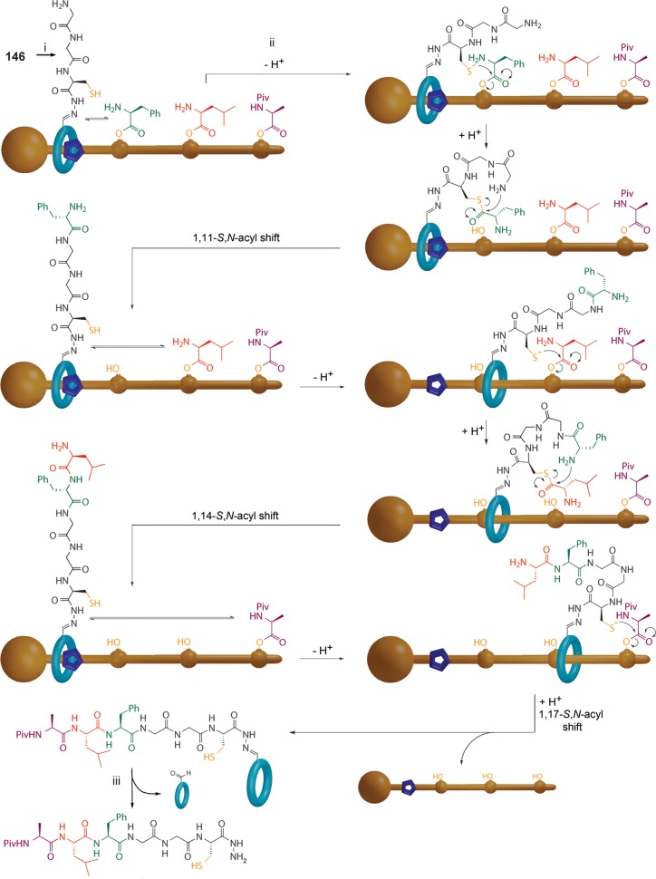
Reprinted with permission
from ref (666). Copyright
2013 American Association for the Advancement of Science (AAAS).
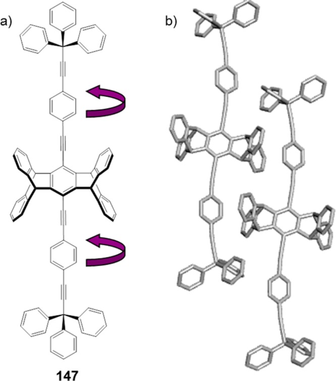
(a) Molecular structure of linear conjugated phenylethynylene molecular
dirotor 147. Rotation of the phenylene rotor (shown with
an arrow) creates rotamers with varying degrees of π-conjugation
and so wavelengths of emission. (b) X-ray structure of the dirotor 147. X-ray crystal structure reprinted with permission from
ref (1462). Copyright
2013 American Chemical Society.
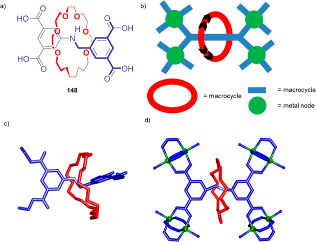
(a)
Structure of [2]rotaxane 148. (b) Schematic representation
of the structural design components used to create the metal–organic
framework. (c) X-ray structure of the tetra-ester precursor to [2]rotaxane 148. (d) X-ray structure of a single unit of the mechanically
interlocked molecule, coordinated to four Cu(II) paddlewheel clusters.
X-ray crystal structure reprinted with permission from ref (1475). Copyright 2012 Nature
Publishing Group.
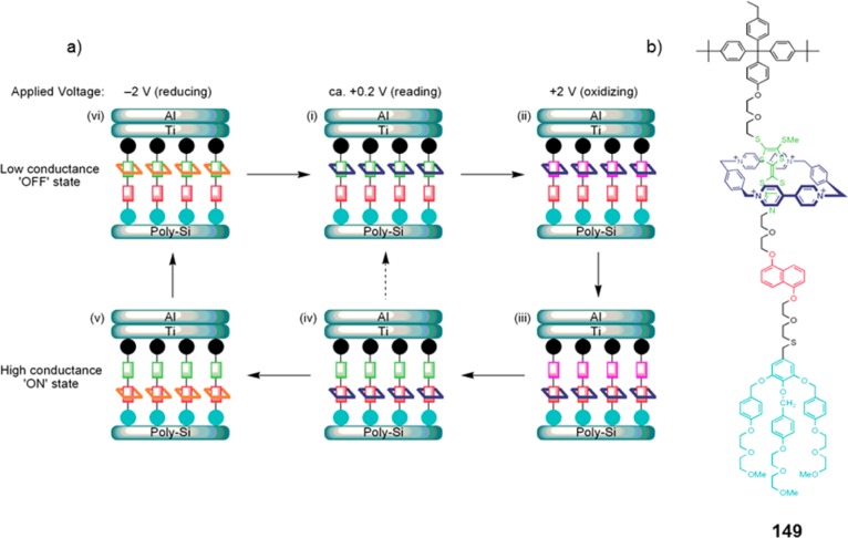
(a) Rotaxane 149-based molecular switch tunnel junctions
and proposed mechanism for the operation. (i) In the ground state,
the tetracationic cyclophane (dark blue) mainly encircles the TTF
station (green) and the junction exhibits low conductance. (ii) Application
of a positive bias results in one- or two-electron oxidation of the
TTF units (green → pink), and increases electrostatic repulsion
causing (iii) shuttling of the macrocycle to the DNP station (red).
(iv) Returning the bias to near −0 V provides a high conductance
state, in which the TTF units have been regenerated, but translocation
of the cyclophane has not yet occurred due to a significant activation
barrier to movement. Thermally activated decay of this metastable
state may occur slowly ((iv) → (i), in a temperature-dependent
manner) or can be triggered by the application of a negative voltage
(v), which temporarily reduces the cyclophane to its diradical dication
form (dark blue → orange), allowing facile recovery of the
thermodynamically favored coconformation (vi). (b) Example of one
design of a molecular switch. The coloring of the functional units
corresponds to that used for the structural diagrams.,, Reprinted with permission from
ref (14). Copyright
2007 Wiley-VCH Verlag GmbH & Co. KGaA, Weinheim.

Color changes in a liquid-crystal film doped
with a light-driven
rotor. Reprinted with permission from ref (1528). Copyright 2002 American National Academy
of Sciences.
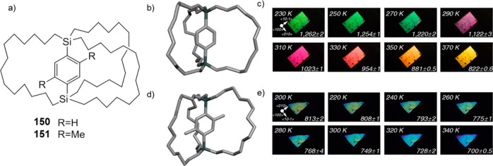
(a) Molecular structure
of gyrotops 150 and 151. The bulkier 151 does not exhibit rotation.
(b) X-ray structure of 150. (c) Single crystal of 150 irradiated with polarized white light. (d) X-ray structure
of 151. (e) Single crystal irradiated with polarized
white light. For 150, a continuous change in color was
observed, due to thermal expansion. Reprinted with permission from
ref (1530). Copyright
2012 American National Academy of Sciences.
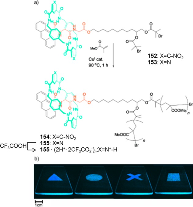
(a) Chemical
structures of rotaxane initiators 152 and 153 and the corresponding PMMA-based polymers 154, 155, and 155·2H2+. (b) Images obtained
by casting films of polymer 154 on quartz slides, then
covering the films with aluminum masks and exposing the unmasked area
to DMSO vapor for 5 min. The photographs were taken while illuminating
the slides with an 8-W UV lamp (254–350 nm). Reprinted with
permission from ref (1536). Copyright 2005 Wiley-VCH Verlag GmbH & Co. KGaA, Weinheim.
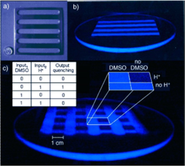
(a) Aluminum
grid used in the experiment. (b) Pattern generated
when films of 155 were exposed to trifluoroacetic acid
vapor for 5 min through the aluminum-grid mask. (c) Mesh pattern obtained
by rotation of the aluminum grid by 90° and exposure of the film
shown in (b) to DMSO vapor for a further 5 min; only regions exposed
to trifluoroacetic acid but not to DMSO were quenched as shown in
the magnified view. Inset: Truth table for an INHIBIT logic gate.
The photographs were taken while illuminating the slides with an 8-W
UV lamp (254–350 nm). Reprinted with permission from ref (1536). Copyright 2005 Wiley-VCH
Verlag GmbH & Co. KGaA, Weinheim.
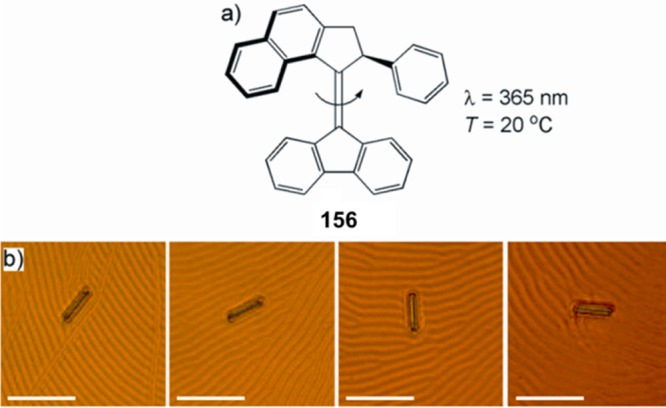
(a) Rotor 156. (b) Rotation of micrometer scale glass
rod on doped liquid crystal film. Photos taken at 15 s intervals.
Reprinted with permission from ref (1637). Copyright 2001 Wiley-VCH Verlag GmbH &
Co. KGaA, Weinheim.

Reprinted with permission
from ref (1647). Copyright
2015 Nature Publishing Group.
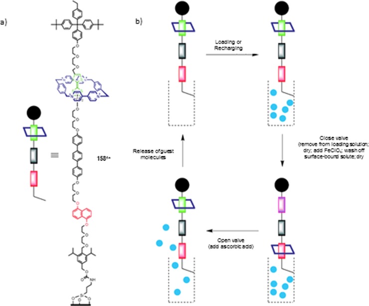
(a) Structure
of nanopore gate, and (b) controlled release of guest
from nanopores. Reprinted with permission
from ref (14). Copyright
2007 Wiley-VCH Verlag GmbH & Co. KGaA, Weinheim.
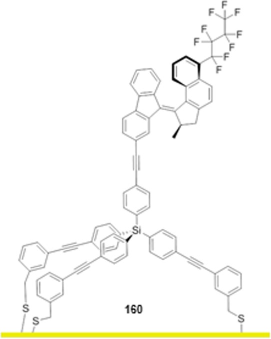
Feringa’s tripodal wettability switch 160.
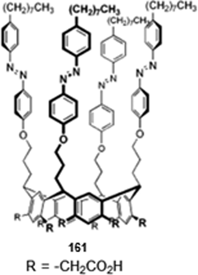
Calix[4]arene 161, used to control surface wettability.
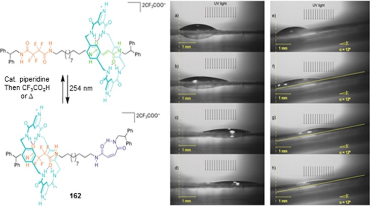
Light switchable rotaxane 162, and transport of a
microliter drop of CH2I2 across a flat surface
(a–d) and up a 12° incline (e–h). Reprinted with
permission from ref (1245). Copyright 2005 Nature Publishing Group.
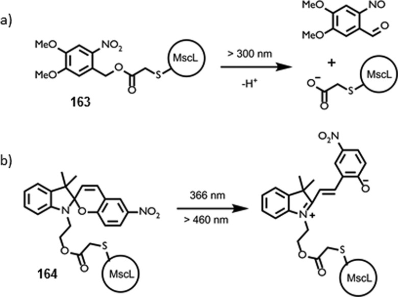
MscL = mechanosensitive channel.
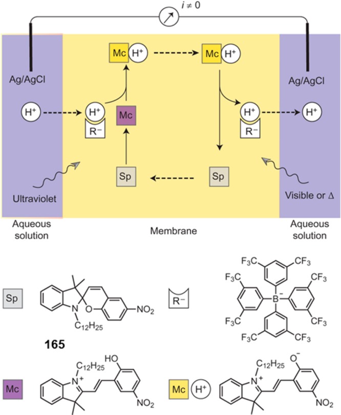
Proton gradient established by spiropyran (165) shuttling
upon differential illumination of the two sides of a membrane. Reprinted
with permission from ref (1809). Copyright 2014 Nature Publishing Group.
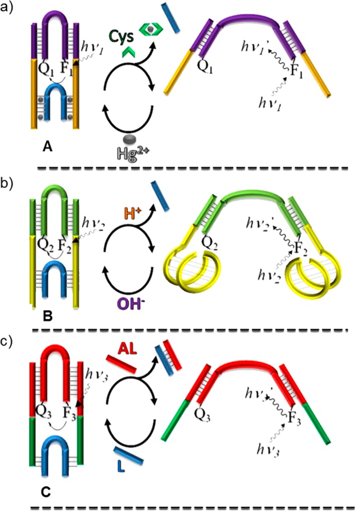
(a) Tweezer A: in the closed form the arms are bound
to the linker unit (blue) by Hg2+ ions through T–Hg2+–T bonds. To open the molecular tweezer, Hg2+ is sequestered by the addition of cysteine. (b) Tweezer B: in acid the arms form an i-motif, thus releasing
the linker unit, whereas at pH = 7.2, the i-motif
is destroyed resulting in the stabilization of the closed structure.
(c) Tweezer C: the linker unit can be released by a complementary
strand, the antilinker that opens the tweezers. Reprinted with permission
from ref (1914). Copyright
2010 American National Academy of Sciences.
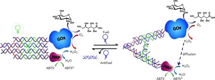
DNA machine reported
by Liu and co-workers, which could be used
to regulate an enzyme cascade reaction. Reprinted with permission
from ref (1915). Copyright
2013 Wiley-VCH Verlag GmbH & Co. KGaA, Weinheim.
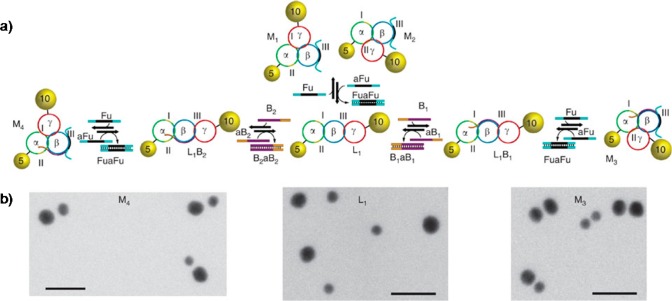
(a) Programmed migration
of two Au nanoparticles. (b) STEM images
corresponding to the different structures; the bar corresponds to
20 nm. Reprinted with permission from ref (1916). Copyright 2013 Nature Publishing Group.
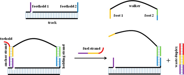
Schematic
representation of a DNA-based walker and track system.
Footholds protrude from the track as single-stranded DNA fragments.
Anchor and holding strands enable the walker unit to bind to the footholds
by hybridization. Areas with functional importance are labeled, and
complementary strands are depicted in the same color for clarity.
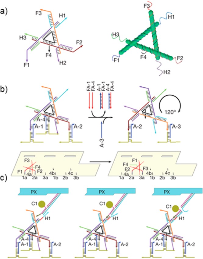
(a) Structure of the DNA walker with four “feet”
(F1–4) and three “hands” (H1–3). (b) Movement
of walker across the DNA origami tile driven by sequentially added
DNA “fuel” strands labeled FA. (c) Loading of cargo
onto DNA walker. Reprinted with permission from ref (1455). Copyright 2010 Nature
Publishing Group.
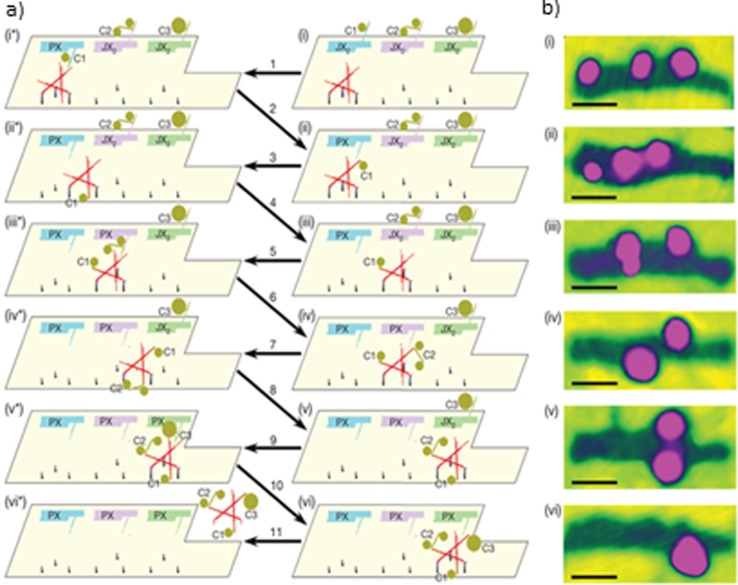
(a) Operation of DNA-based
walker. (b) AFM images of walker. Reprinted
with permission from ref (1455). Copyright 2010 Nature Publishing Group.
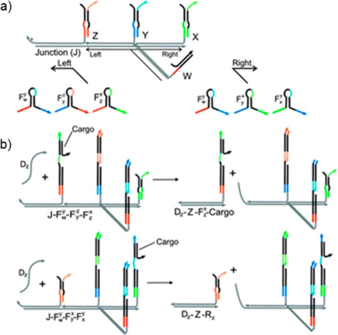
Walker with a choice of path at a junction. (a) Initially cargo
resides on position W, and (b) the use of different set of fuels (F)
leads to transport of cargo to either position. A displacing strand
(Dz) was used for the fragmentation of the molecular ensemble and
subsequent analysis of the cargo position. Reprinted with permission
from ref (1843). Copyright
2011 American Chemical Society.
References
-
- Brown R. A Brief Account of Microscopical Observations Made on the Particles Contained in the Pollen of Plants. Philos. Mag. 1828, 4, 171–17310.1080/14786442808674769. - DOI
-
- Brown R. On the Particles Contained in the Pollen of Plants; and on the General Existence of Active Molecules in Organic and Inorganic Bodies. Edinb. New Philos. J. 1828, 5, 358–371.
-
- Perrin J. In Atoms (English Translation), 2nd ed.; Hammick D. L., Ed.; Constable and Co.: London, 1923.
-
- Einstein A. Über die von der Molekularkinetischen Theorie der Wärme Geforderte Bewegung von in Ruhenden Flüssigkeiten Suspendierten Teilchen. Ann. Phys. 1905, 17, 549–56010.1002/andp.19053220806. - DOI
-
- Feynman R. P.; Leighton R. B.; Sands M.. The Feynman Lectures on Physics; Addison-Wesley: Reading, MA, 1963; Vol. 1, Chapter 46.
Publication types
MeSH terms
Substances
LinkOut - more resources
Full Text Sources
Other Literature Sources
