. 2015 Sep 8:6:8092.
doi: 10.1038/ncomms9092.

Dynamic kirigami structures for integrated solar tracking

Affiliations

Dynamic kirigami structures for integrated solar tracking

Aaron Lamoureux et al. Nat Commun. .

Abstract

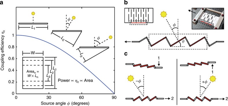
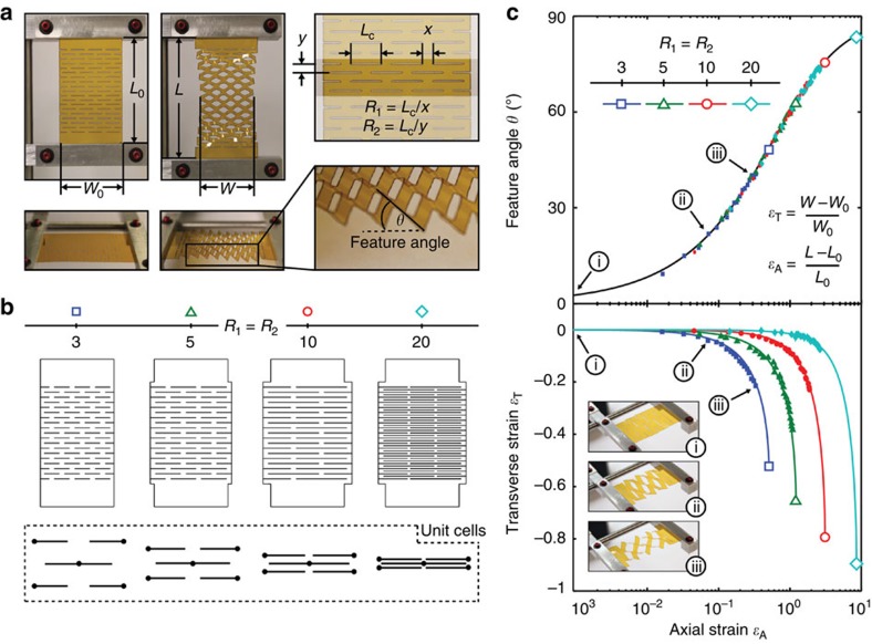
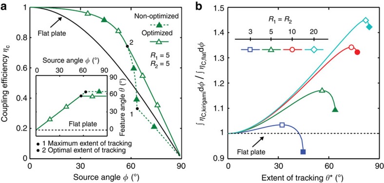
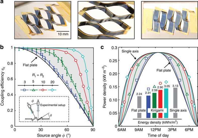
Optical tracking is often combined with conventional flat panel solar cells to maximize electrical power generation over the course of a day. However, conventional trackers are complex and often require costly and cumbersome structural components to support system weight. Here we use kirigami (the art of paper cutting) to realize novel solar cells where tracking is integral to the structure at the substrate level. Specifically, an elegant cut pattern is made in thin-film gallium arsenide solar cells, which are then stretched to produce an array of tilted surface elements which can be controlled to within ±1°. We analyze the combined optical and mechanical properties of the tracking system, and demonstrate a mechanically robust system with optical tracking efficiencies matching conventional trackers. This design suggests a pathway towards enabling new applications for solar tracking, as well as inspiring a broader range of optoelectronic and mechanical devices.


Figures

Figure 1
Figure 1. Optical coupling efficiency and novel kirigami trackers.
(a) Coupling efficiency (ηC) versus source angle (φ) for a planar solar panel. The panel projected area decreases with the cosφ. (b) A kirigami tracking structure that, upon stretching, simultaneously changes the angle of the elements comprising the sheet. By incorporating thin-film solar cells into this structure, it may be used as a low-profile alternative to conventional single-axis solar tracking. (c) The direction of feature tilt (that is, clockwise or counter-clockwise with respect to the original plane) is controlled by lifting or lowering one end of the sheet (step 1) before the straining process (step 2).
Figure 2
Figure 2. Kirigami cut geometry and geometric system response.
(a) Response of a Kapton kirigami structure to stretching in the axial direction (ɛA) is accompanied by a decrease in sample width (ɛT) and a change in feature angle (θ). Also shown are the geometric parameters that define the kirigami structure, namely the cut length (LC) and spacing between cuts in the transverse (x) and axial (y) directions, which can be expressed in terms of the dimensionless parameters, R1 and R2. (b) Schematics of four kirigami structures, where R1=R2=3, 5, 10 and 20, along with their corresponding units cells. (c) ɛT and θ versus ɛA for several kirigami structures where R1=R2=3, 5, 10 and 20 (b). Theoretical predictions per equations (1) and (2) are shown by solid lines, while the closed symbols represent experimental data from a 50 μm-thick Kapton sample of the appropriate geometry. While larger R1 and R2 enable increased axial strains and correspondingly larger transverse strains, the change in feature angle is independent of cut geometry.
Figure 3
Figure 3. Optimization of tracking process to maximize coupling efficiency.
(a) Coupling efficiency (ηC) versus source angle (φ) for two systems with different extent of tracking (θ*). Inset: Feature angle (θ) versus φ. Non-optimized tracking (closed symbols) close to the geometric maximum (θMAX, point 1) results in a sharp decrease in sample width that decreases optical coupling efficiency. Instead, coupling efficiency is optimized (open symbols) by a tradeoff between sample narrowing, self-shadowing, and cosine losses (c.f. equation (4) in text) corresponding instead to an optimal angle (point 2). Simulated system response is shown for R1=R2=5, and is compared to a conventional non-tracking panel. (b) Coupling efficiency, ηC integrated over a range of tracking angle (from φ=0 to φ=θ*) and normalized to conventional planar cell performance. For a given kirigami structure, optimal performance is obtained by tracking the source at normal incidence to θ* corresponding to the maximum of each curve. For comparison, tracking to θMAX versus tracking to the optimal θ* is shown as solid and open symbols, respectively.
Figure 4
Figure 4. Tracking performance for GaAs kirigami trackers.
(a) Integrated thin-film, crystalline GaAs solar cells, mounted by cold weld bonding on a Kapton carrier substrate, as used for testing. Here, LC=15 mm, x=5 mm and y=5 mm (R1=R2=3). (b) Normalized solar cell short circuit current density JSC(φ)/JSC(φ=0) for two samples, where R1=R2=3 and R1=R2=5 (closed symbols). Also shown are the simulated data for coupling efficiency (ηC) obtained from equation (4) (solid lines, open symbols). The agreement between experimental and simulated results suggests that ηC is a direct measure of optical coupling, and that performance may be optimized by increasing R1 and R2. (c) Output electrical power density incident on the solar cell versus time of day for several kirigami cut structures, stationary panel and single-axis tracking systems in Phoenix, AZ (33.45° N, 112.07° W) during the summer solstice. Inset: Integration of the curves yields the associated energy densities, where kirigami-enabled tracking systems are capable of near single-axis performance.

References

    1. Mousazadeh H. et al. A review of principle and sun-tracking methods for maximizing solar systems output. Renew. Sust. Energ. Rev. 13, 1800–1818 (2009).
    1. Lee C. Y., Chou P. C., Chiang C. M. & Lin C. F. Sun tracking systems: a review. Sensors 9, 3875–3890 (2009). - PMC - PubMed
    1. Feuermann D. & Gordon J. High-concentration photovoltaic designs based on miniature parabolic dishes. Sol. Energy 70, 423–430 (2001).
    1. Sierra C. & Vazquez A. J. High solar energy concentration with a Fresnel lens. J. Mater. 40, 1339–1343 (2005).
    1. Ryu K., Rhee J., Park K. & Kim J. Concept and design of modular Fresnel lenses for concentration solar PV system. Sol. Energy 80, 1580–1587 (2006).

Publication types