. 2015 Sep 10:6:8241.
doi: 10.1038/ncomms9241.

Helicity multiplexed broadband metasurface holograms

Affiliations

Helicity multiplexed broadband metasurface holograms

Dandan Wen et al. Nat Commun. .

Abstract

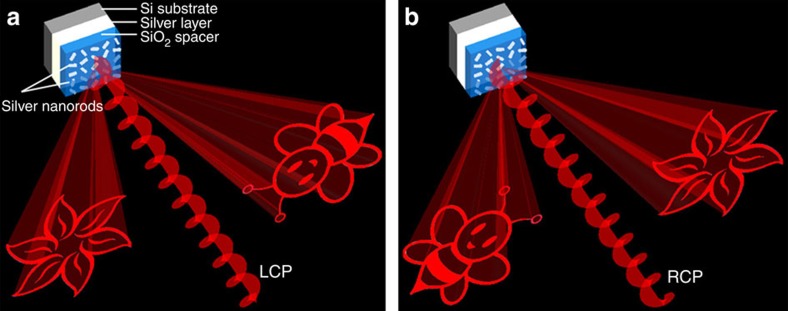
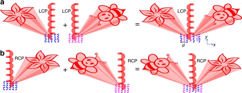
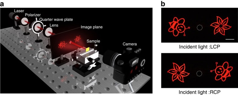
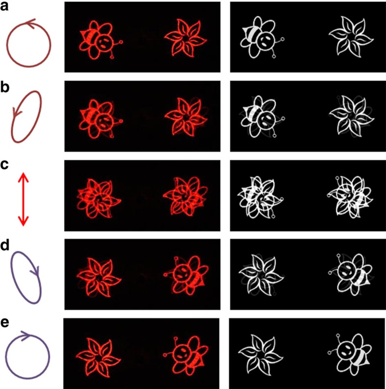
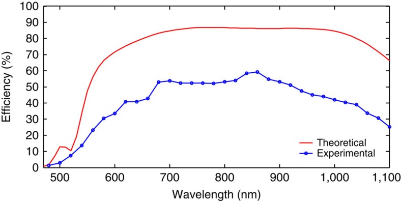
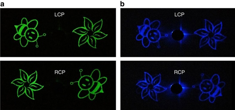
Metasurfaces are engineered interfaces that contain a thin layer of plasmonic or dielectric nanostructures capable of manipulating light in a desirable manner. Advances in metasurfaces have led to various practical applications ranging from lensing to holography. Metasurface holograms that can be switched by the polarization state of incident light have been demonstrated for achieving polarization multiplexed functionalities. However, practical application of these devices has been limited by their capability for achieving high efficiency and high image quality. Here we experimentally demonstrate a helicity multiplexed metasurface hologram with high efficiency and good image fidelity over a broad range of frequencies. The metasurface hologram features the combination of two sets of hologram patterns operating with opposite incident helicities. Two symmetrically distributed off-axis images are interchangeable by controlling the helicity of the input light. The demonstrated helicity multiplexed metasurface hologram with its high performance opens avenues for future applications with functionality switchable optical devices.


Figures

Figure 1
Figure 1. Schematics of the helicity multiplexed metasurface hologram.
The reflective-type metasurface consists of silver nanorods with spatially varying orientations on the top, a SiO2 spacer (80 nm) and a silver background layer (150 nm) resting on a silicon substrate. (a) Under the illumination of LCP light, the holographic images ‘flower' and ‘bee' are reconstructed on the left and right side viewing from direction of the incident light, respectively. (b) The positions of the two holographic images are swapped when the helicity of incident light changes from LCP to RCP. The circularly polarized light impinges the reflective-type metasurface at normal incidence and the reflected light that contributes to the images has the same polarization as that of the incident light.
Figure 2
Figure 2. Generation of the helicity multiplexed metasurface hologram.
Two sets of hologram patterns are designed to operate with opposite incident helicities and merged together with a displacement vector of (d/2, d/2). d is the distance between neighbouring antennas with a value of 424 nm along x and y directions. (a) Upon the illumination of LCP light at normal incidence, the reconstructed ‘flower' and the ‘bee' are on the left side and on the right side of the incident beam, respectively. The two off-axis images are symmetrically distributed. The blue nanorods and purple nanorods represent the metasurface holograms for ‘flower' and ‘bee', respectively. (b) The position for the ‘flower' and that for the ‘bee' are swapped on the illumination of RCP light.
Figure 3
Figure 3. The designed metasurface hologram and the fabricated sample.
(a) Geometric parameters of the projected images that correspond to the merged hologram. The full off-axis angle α1, target image angles α2 and α3 are designed to be 20.7°, 22° and 64.7°, respectively. (b) Phase delay for the different phase levels. Sixteen phase levels (−π to π with the interval of π/8) are used in the design. On each red point, the orientation of the corresponding nanorod is given. The orientation of each nanorod is defined as the angle between the long axis of the nanorod and the y axis. (c) Schematic of the nanorod distribution for the merged metasurface hologram. The phase levels are denoted by the different colours of the nanorods. The nanorods in the rows with odd number and even number contribute to the reconstruction of ‘bee' and ‘flower', respectively. (d) Scanning electron microscopy image of part of the fabricated metasurface. Each nanorod represents a phase pixel defined in the hologram. Scale bar, 1 μm. The equivalent pixel size is 300 × 300 nm2.
Figure 4
Figure 4. Illustration of the experiment set-up and the experimental results.
(a) The incident light with various polarization states is obtained by controlling the angle θ between the polarization axis of the polarizer and the fast axis of the quarter-wave plate. The incident light impinges normally onto the metasurface and the reconstructed images are projected onto the image plane. The screen is a white paper board with an opening (diameter 6 mm) in the middle, which allows the incident light and zero order reflected light passing through. (b) The experimentally obtained images for the incident light with LCP (top) and RCP (bottom). The wavelength of the incident light is 633 nm. The dashed circles mark the edge of the opening. Scale bar, 1 cm.
Figure 5
Figure 5. Reconstructed images versus incident polarization states at 633 nm.
The polarization states of the incident light are chosen to be (a) LCP, (b) left-handed elliptically polarized, (c) linearly polarized, (d) right-handed elliptically polarized and (e) RCP. The figures in the middle column and right column represent the experimental results and the corresponding simulation results, respectively.
Figure 6
Figure 6. Conversion efficiency of the metasurface hologram.
The conversion efficiency is defined as the power of ‘bee' and ‘flower' divided by the power of the incident light. The blue circles represent the experimentally measured efficiencies over a broad range of wavelengths. The titanium layer is not considered in the simulation.
Figure 7
Figure 7. Experimentally obtained images at other visible wavelengths.
The wavelengths of the incident light are (a) 524 nm and (b) 475 nm, respectively.

References

    1. Xu F., Ford J. E. & Fainman Y. Polarization-selective computer-generated holograms: design, fabrication, and applications. Appl. Opt. 34, 256–266 (1995). - PubMed
    1. Krishnamoorthy A. V., Xu F., Ford J. E. & Fainman Y. Polarization-controlled multistage switch based on polarization-selective computer-generated holograms. Appl. Opt. 36, 997–1010 (1997). - PubMed
    1. Ford J. E., Xu F., Urquhart K. & Fainman Y. Polarization-selective computer-generated holograms. Opt. Lett. 18, 456–458 (1993). - PubMed
    1. Yu W. et al. Polarization-multiplexed diffractive optical elements fabricated by subwavelength structures. Appl. Opt. 41, 96–100 (2002). - PubMed
    1. Kostuk R. K., Kato M. & Huang Y. T. Polarization properties of substrate-mode holographic interconnects. Appl. Opt. 29, 3848–3854 (1990). - PubMed

Publication types