

Review
doi: 10.1557/mrc.2015.6.
The expanding world of hybrid perovskites: materials properties and emerging applications
Affiliations
- PMID: 26366326
- PMCID: PMC4563667
- DOI: 10.1557/mrc.2015.6
Item in Clipboard
Review
The expanding world of hybrid perovskites: materials properties and emerging applications
MRS Commun.
2015 Mar.
Abstract
Figures
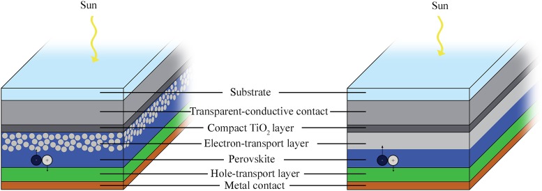
Comparison of the mesoporous (left) and planar (right) architectures used in perovskite solar cells. Most devices with high efficiency use glass/FTO/TiO2/CH3NH3PbI3/Spiro-OMeTAD/Au. Except for the glass substrate, layer thicknesses are drawn approximately to scale.
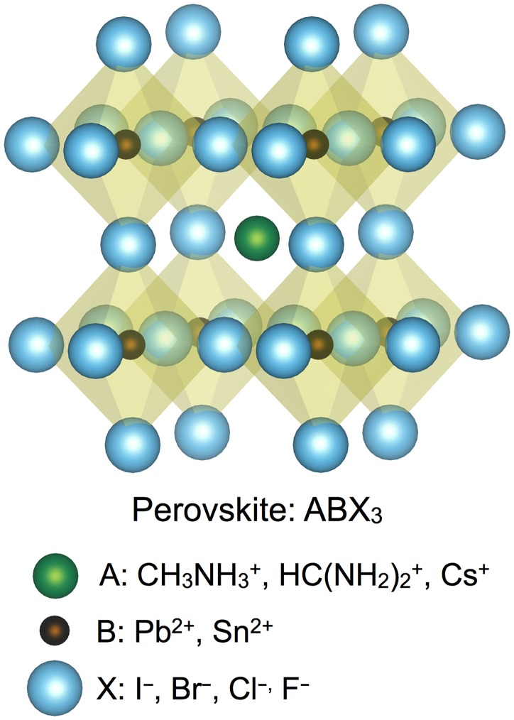
The perovskite crystal structure with the general form ABX3, in which A+ is confined within a cage determined by the octahedral coordination of B2+ with X− anions. The sizes of the spheres are given by the ionic radii of CH3NH3+, Pb2+, and I−.[13,17] The most common cations and anions that have been used in each position within the 3D halide perovskites are listed. The wider variety of materials that have been used in 2D halide hybrid perovskites can be found in the review by Mitzi.[31]
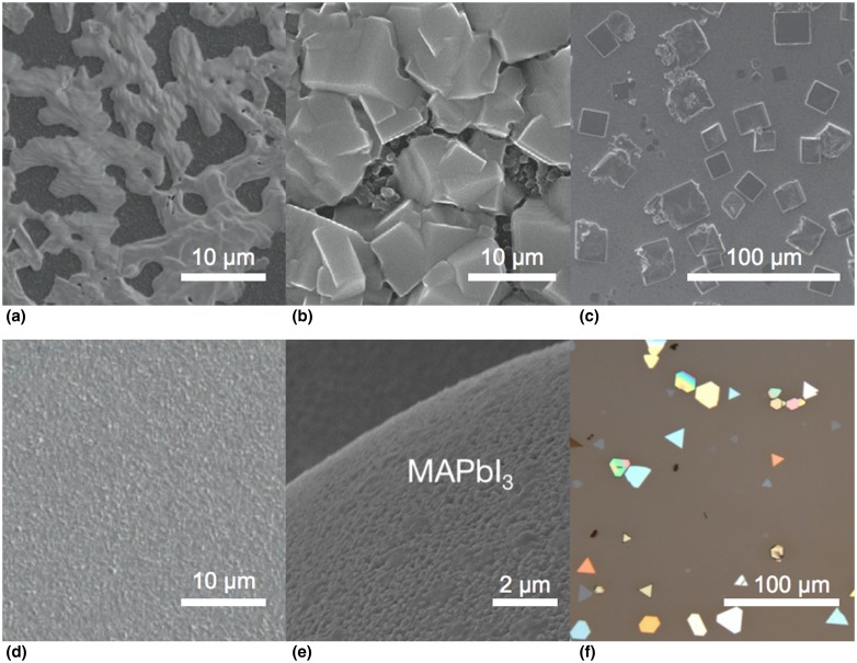
A gallery of morphologies of the hybrid perovskites. SEM images of (a) solution-deposited CH3NH3PbI3–xClx, (b) CH3NH3PbI3 deposited by the two-step solution method, (c) crystals of CH3NH3PbBr3 deposited from DMF solution, (d) CH3NH3PbI3–xClx deposited by co-evaporation of PbCl2 and CH3NH3I in vacuum, and (e) a microsphere conformally coated with CH3NH3PbI3 produced by the conversion of PbS deposited by atomic-layer deposition. (f) An optical image of CH3NH3PbI3 platelets synthesized by the two-step process in vapor phase. Panels (a) and (d) are reproduced with permission from Ref. . Copyright 2013, Nature Publishing Group. Panel (b) is reproduced with permission from Ref. . Copyright 2014, Nature Publishing Group. Panel (c) is reproduced with permission from Ref. . Copyright 2014, Wiley-VCH Verlag GmbH & Co. Panel (e) is reproduced with permission from Ref. . Copyright 2014, Wiley-VCH Verlag GmbH & Co. Panel (f) is reproduced with permission from Ref. . Copyright 2014, American Chemical Society.
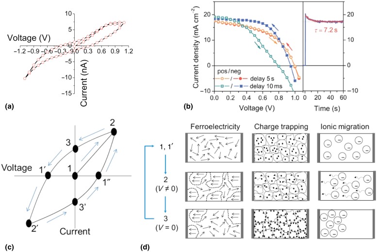
Hysteresis in the electrical transport in hybrid perovskites. (a) I–V measurement taken at room temperature on a single crystal of CH3NH3PbI3 exhibiting pronounced hysteresis. (b) The I–V characteristic (left) of a perovskite solar cell depends upon the rate at which the voltage is scanned: in this specific case, more hysteresis is observed for the faster scan rate. The photocurrent stabilizes with a long time constant of 7.2 s (right). Schematic hysteretic I–V curve (c) and phenomena proposed for its origin (d). The as-synthesized perovskite exists in a disordered state (1). When a bias is applied (2), the electric field creates a change in the material, as depicted in (d) for the three proposed mechanisms. Upon return of the field back to 0 V (3), the arrangement of dipoles, trapped charges, or ions has been altered from the initial state, so current continues to flow as this configuration relaxes, creating hysteresis. The material returns to its initial state (1′) upon application of a negative bias. The same process with reversed polarity occurs for points 2′, 3′, and 1″. Panel (a) is reproduced with permission from the supporting information from Ref. . Copyright 2013, American Chemical Society. Panel (b) is reproduced with permission from Ref. . Copyright 2014, Royal Society of Chemistry.
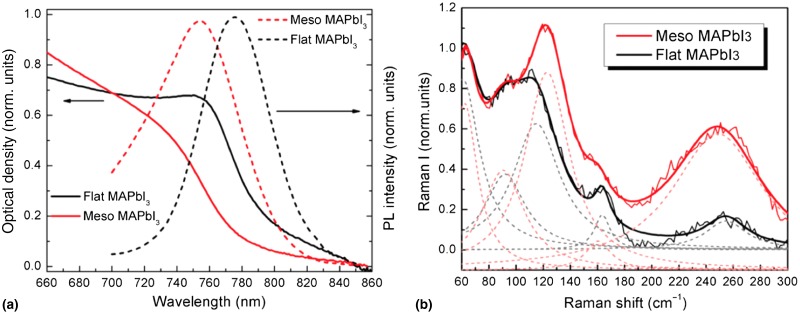
Absorption and PL spectra (a) and resonant Raman spectra (b) of CH3NH3PbI3 deposited on flat substrates and in mesoporous substrates. Clearly the optical properties of the material depend sensitively on the material's structure, which is determined in part by the substrate on which it is deposited. Solid lines in (b) are the sums of the individual peaks (dotted lines) used to fit the spectra. The figure is reproduced with permission from Ref. . Copyright 2014, American Chemical Society.

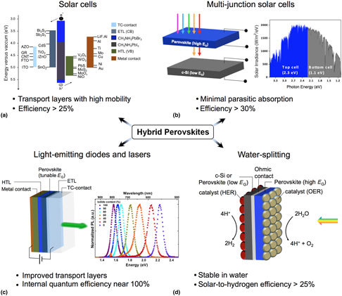
Targets for emerging applications of hybrid perovskites. The success of single-junction photovoltaics has paved the way for other applications of hybrid perovskites. Improvements can be made in the contacting of perovskites for higher efficiency solar cells (a), and perovskites can be combined with crystalline silicon for an efficient yet inexpensive tandem solar cell (b). Additionally, emission of light in the form of LEDs or lasers holds much promise (c). If the perovskites’ instability in water can be overcome, perhaps through encapsulation, then their tunable band gap makes them an attractive option for solar water-splitting (d). Transparent-conducting contact, TC-contact; electron-transport layer, ETL; hole-transport layer, HTL; valence band, VB; conduction band, CB; aluminum-doped ZnO, AZO; graphene, GR; carbon nanotubes, CNT; fluorine-doped and indium tin oxide, FTO and ITO; hydrogen and oxygen evolution reaction, HER and OER. The PL spectra included in the figure are reproduced with permission from Ref. . Copyright 2014, American Chemical Society.
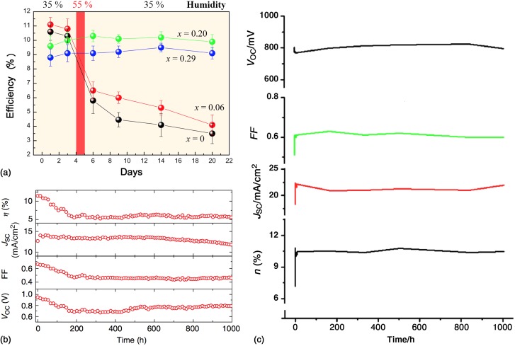
(a) Comparison of the stability of solar cells made from mixed perovskites CH3NH3Pb(I1−xBrx)3. Devices were stored in air without encapsulation and tested periodically. On the fourth day the devices were exposed to 55% humidity to evaluate the effect of water on their stability. (b) Stability of a solar cell made from CH3NH3PbI3−xClx on an alumina scaffold under continuous illumination of 76.5 mW/cm2 (~3/4 one-sun intensity) at 40 °C. The device was encapsulated in a nitrogen environment. (c) Stability over 42 days (1008 h) of a perovskite solar cell made from mixed organic cations CH3NH3PbI3 and 5-ammoniumvaleric acid. The unsealed device was continuously illuminated under one-sun, A.M. 1.5 conditions in air, although the carbon back contact is expected to provide some encapsulation. Panel (a) is reproduced with permission from Ref. , copyright 2013, American Chemical Society. Panel (b) is reproduced with permission from Ref. . Copyright 2013, Nature Publishing Group. Panel (c) is adapted with permission from the supplementary materials from Ref. . Copyright 2013, American Association for the Advancement of Science.
References
-
- Green M.A., Emery K., Hishikawa Y., Warta W., and Dunlop E.D.: Solar cell efficiency tables (version 45). Prog. Photovolt. Res. Appl. 23, 1 (2015).
-
- Kojima A., Teshima K., Shirai Y., and Miyasaka T.: Organometal halide perovskites as visible-light sensitizers for photovoltaic cells. J. Am. Chem. Soc. 131, 6050 (2009). - PubMed
-
- Kim H.-S., Lee C.-R., Im J.-H., Lee K.-B., Moehl T., Marchioro A., Moon S.-J., Humphry-Baker R., Yum J.-H., Moser J.E., Grätzel M., and Park N.-G.: Lead iodide perovskite sensitized all-solid-state submicron thin film mesoscopic solar cell with efficiency exceeding 9%. Sci. Rep. 2, 591 (2012). - PMC - PubMed
-
- Liu M., Johnston M.B., and Snaith H.J.: Efficient planar heterojunction perovskite solar cells by vapour deposition. Nature 501, 395 (2013). - PubMed
-
- Luo J., Im J.-H., Mayer M.T., Schreier M., Nazeeruddin M.K., Park N.-G., Tilley S.D., Fan H.J., and Gratzel M.: Water photolysis at 12.3% efficiency via perovskite photovoltaics and earth-abundant catalysts. Science 345, 1593 (2014). - PubMed
Publication types
LinkOut - more resources
Full Text Sources
Other Literature Sources