. 2015 Sep 16;10(9):e0138258.
doi: 10.1371/journal.pone.0138258. eCollection 2015.

Generalization of Dexterous Manipulation Is Sensitive to the Frame of Reference in Which It Is Learned

Affiliations

Generalization of Dexterous Manipulation Is Sensitive to the Frame of Reference in Which It Is Learned

Michelle Marneweck et al. PLoS One. .

Abstract

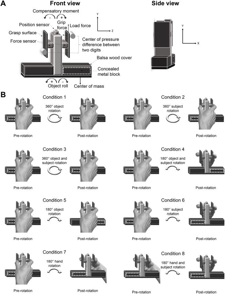
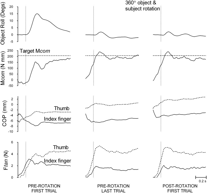
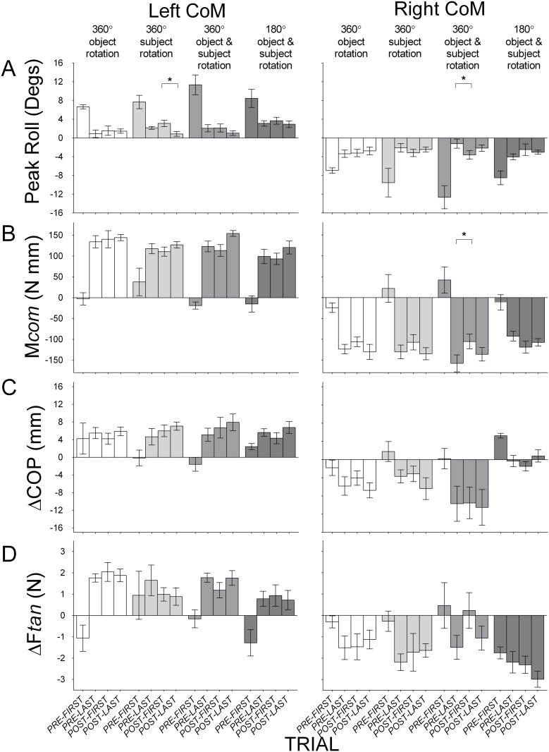
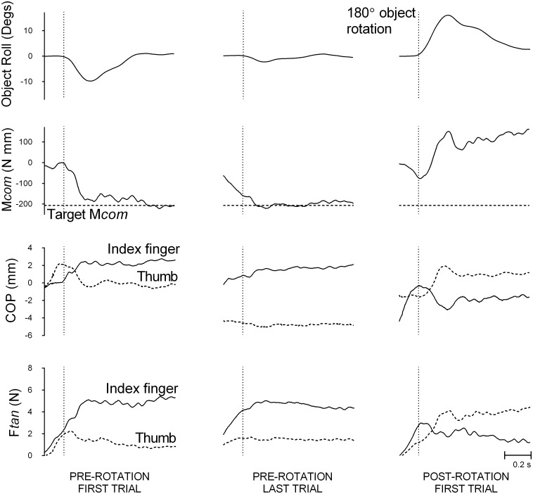
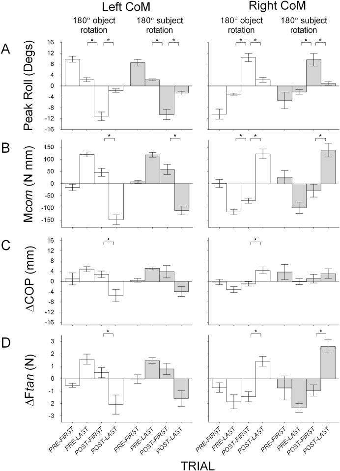
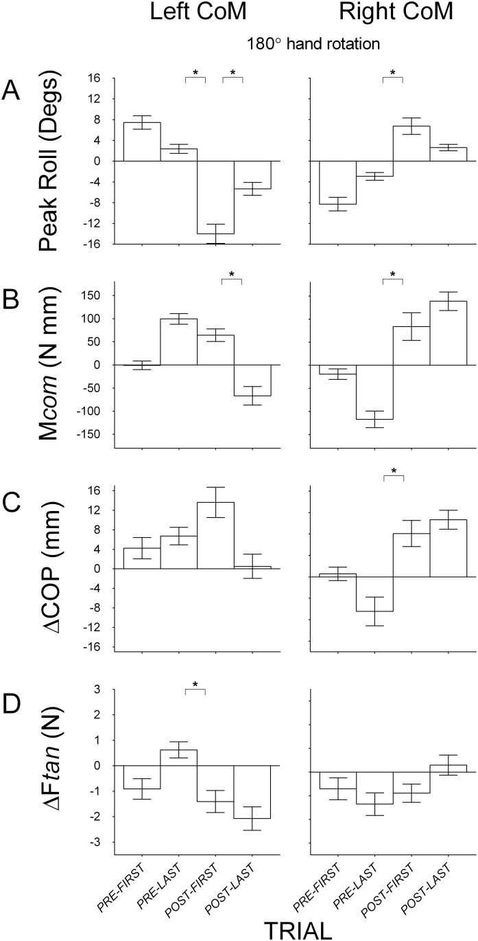
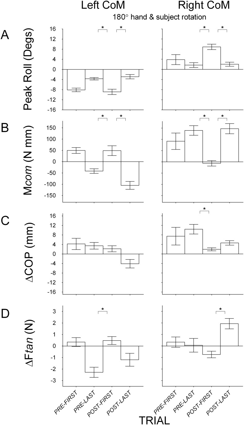
Studies have shown that internal representations of manipulations of objects with asymmetric mass distributions that are generated within a specific orientation are not generalizable to novel orientations, i.e., subjects fail to prevent object roll on their first grasp-lift attempt of the object following 180° object rotation. This suggests that representations of these manipulations are specific to the reference frame in which they are formed. However, it is unknown whether that reference frame is specific to the hand, the body, or both, because rotating the object 180° modifies the relation between object and body as well as object and hand. An alternative, untested explanation for the above failure to generalize learned manipulations is that any rotation will disrupt grasp performance, regardless if the reference frame in which the manipulation was learned is maintained or modified. We examined the effect of rotations that (1) maintain and (2) modify relations between object and body, and object and hand, on the generalizability of learned two-digit manipulation of an object with an asymmetric mass distribution. Following rotations that maintained the relation between object and body and object and hand (e.g., rotating the object and subject 180°), subjects continued to use appropriate digit placement and load force distributions, thus generating sufficient compensatory moments to minimize object roll. In contrast, following rotations that modified the relation between (1) object and hand (e.g. rotating the hand around to the opposite object side), (2) object and body (e.g. rotating subject and hand 180°), or (3) both (e.g. rotating the subject 180°), subjects used the same, yet inappropriate digit placement and load force distribution, as those used prior to the rotation. Consequently, the compensatory moments were insufficient to prevent large object rolls. These findings suggest that representations of learned manipulation of objects with asymmetric mass distributions are specific to the body- and hand-reference frames in which they were learned.


Conflict of interest statement

Competing Interests: The authors have declared that no competing interests exist.

Figures

Fig 1
Fig 1. A depiction of the visually symmetrical object with a visually concealed asymmetric mass distribution, and the experimental procedure for the 8 conditions.
(A) Custom built inverted T-shaped object. A solid brass metal block was placed on either the left or right side on the base of the object. The solid brass metal block was visually concealed with two balsa wood covers that were placed on the left and right side on the base of the object. Thus, the object was symmetrical in appearance but not in mass distribution. An electromagnetic position sensor was placed at the top of the vertical column to measure object roll. The grasp surfaces were attached to the force sensors that measured forces and centers of pressure of the thumb and index finger. Left and right panels show front and side views of the object; (B) Experimental procedures for each of the 8 conditions during pre-rotation trials (with the center of mass on the left; see white dotted outline) and following a rotation, the post-rotation trials. The rotation either maintained hand and body reference frames (Condition 1–4) or modified hand and/or body reference frames (Conditions 5–8). Conditions that maintained hand and body reference frames involved a 360° object rotation (Condition 1), 360° subject rotation (Condition 2), 360° object and subject rotation (Condition 3), and a 180° object and subject rotation (Condition 4). Conditions that modified hand and/or body reference frames involved a 180° object rotation (Condition 5), 180° subject rotation (Condition 6), 180° hand rotation (Condition 7), and a 180° hand and subject rotation (Condition 8). A full circle arrow indicates a 360° rotation (by object and/or subject, dependent on condition), and a half circle arrow indicates a 180° rotation (by object/and or subject and/or hand, dependent on condition).
Fig 2
Fig 2. A representative subject’s performance traces in a condition that maintains object-subject and object-body relations.
(A) Object roll; (B) Compensatory moment (Mcom, solid line) and target Mcom (dotted line, plotted as same sign as Mcom for graphical purposes); (C) center of pressure (COP) by the thumb (dotted line) and the index finger (solid line); (D) Load force (Ftan) by the index finger (solid line) and the thumb (dotted line). Data are shown for the first (left panel) and last pre-rotation trial (middle panel), and following a rotation that does not modify the relation between the object and body, and object and hand (Condition 3), the first post-rotation trial (right panel), with the object’s CoM on the left. The vertical dotted line represents the lift onset time.
Fig 3
Fig 3. Group means (± 1 standard error) for Conditions 1–4 that maintain object-hand and object-body relations.
(A) Object roll with positive and negative values indicating roll towards the thumb and the index finger respectively; (B) Compensatory moment (Mcom) with positive and negative values indicating moments generated away from the thumb and the index finger respectively; (C) Vertical distance between the thumb and the index finger center of pressure (ΔCOP) with positive values indicating higher thumb placement than index finger placement and negative values indicating higher index finger placement than thumb placement; (D) Difference in load force (ΔFtan) by the thumb and the index finger with positive values indicating more force by the thumb than the index finger and negative values indicating more force by the index finger than the thumb. Data are shown for the first and last pre-rotation trial, and the first and last post-rotation trial, with the object’s CoM on the left (left panel) and on the right (right panel) during pre-rotation trials, for Condition 1 (360° rotation of object; clear), Condition 2 (360° rotation of subject; light gray), Condition 3 (360° rotation of object and subject; medium gray) and Condition 4 (180° rotation of object and subject; dark gray). The first pre-rotation trial for the left and right CoM blocks in each condition is only shown for half of the subjects (because half started the task with the object’s CoM on the left and right, respectively). Statistically significant differences between the first post-rotation trial and the last pre-rotation and between the first post-rotation trial and the last post-rotation trial are denoted with an asterisk (p < 0.05).
Fig 4
Fig 4. A representative subject’s performance traces by in a condition that modifies object-subject and object-body relations.
(A) Object roll; (B) Compensatory moment (Mcom, solid line) and target Mcom (dotted line, plotted as same sign as Mcom for graphical purposes); (C) Center of pressure (COP) by the thumb (dotted line) and the index finger (solid line); (D) Load force (Ftan) by the thumb (dotted line) and the index finger (solid line). Data are shown for the first (left panel) and last pre-rotation trial (middle panel) with the object’s CoM on the right and, following a rotation that modifies both the relation between the object and body and object and hand (Condition 5), the first post-rotation trial (right panel). The vertical dotted line represents the lift onset time.
Fig 5
Fig 5. Group means (±1 standard error) for Conditions 5–6 that modify object-hand and object-body relations.
(A) Object roll with positive and negative values indicating roll towards the thumb and the index finger respectively; (B) Compensatory moment (Mcom) with positive and negative values indicating moments generated away from the thumb and the index finger respectively; (C) Vertical distance between the thumb and the index finger center of pressure (ΔCOP) with positive values indicating higher thumb than index finger placement and negative values indicating higher index finger than thumb placement; (D) Difference in load force (ΔFtan) by the thumb and the index finger with positive values indicating more force by the thumb than the index finger and negative values indicating more force by the index finger than the thumb. Data are shown for the first and last pre-rotation trial, and the first last post-rotation trial, with the object’s CoM on the left (left panel) and on the right (right panel) during pre-rotation trials, for Condition 5 (180° rotation of object; clear) and Condition 6 (subject (180° rotation of subject; light gray). The first pre-rotation trial for the left and right CoM blocks in each condition is only shown for half of the subjects (because half started the task with the object’s CoM on the left and right, respectively). Statistically significant differences between the first post-rotation trial and the last pre-rotation and between the first post-rotation trial and the last post-rotation trial are denoted with an asterisk (p < 0.05).
Fig 6
Fig 6. Group means (± 1 standard error) for Condition 7 that modifies the object-hand relation.
(A) Object roll with positive and negative values indicating roll towards the thumb and the index finger respectively; (B) Compensatory moment (Mcom) with positive and negative values indicating moments generated away from the thumb and the index finger respectively; (C) Vertical distance between the thumb and the index finger center of pressure (ΔCOP) with positive values indicating higher thumb than index finger placement and negative values indicating higher index finger than thumb placement, and; (D) Difference in load force (ΔFtan) by the thumb and the index finger with positive values indicating more force by the thumb than the index finger and negative values indicating more force by the index finger than the thumb. Data are shown for the first and last pre-rotation trial, and for the first and last post-rotation trial, with the object’s CoM on the left (left panel) and on the right (right panel) during pre-rotation trials. The first pre-rotation trial for the left and right CoM blocks is only shown for half of the subjects (because half started the task with the object’s CoM on the left and right, respectively). Statistically significant differences between the first post-rotation trial and the last pre-rotation and between the first post-rotation trial and the last post-rotation trial are denoted with an asterisk (p < 0.05).
Fig 7
Fig 7. Group means (± 1 standard error) for Condition 8 that modifies the object-body relation.
(A) Object roll with positive and negative values indicating roll towards the thumb and the index finger respectively; (B) Compensatory moment (Mcom) with positive and negative values indicating moments generated away from the thumb and the index finger respectively; (C) Vertical distance between the thumb and the index finger center of pressure (ΔCOP) with positive values indicating higher thumb than index finger placement and negative values indicating higher index finger than thumb placement; (D) Difference in load force (ΔFtan) by the thumb and the index finger with positive values indicating more force by the thumb than the index finger and negative values indicating more force by the index finger than the thumb. Data are shown for the first and last pre-rotation trial, and for the first and last post-rotation trial, with the object’s CoM on the left (left panel) and on the right (right panel) during pre-rotation trials. The first pre-rotation trial for the left and right CoM blocks is only shown for half of the subjects (because half started the task with the object’s CoM on the left and right, respectively). Statistically significant differences between the first post-rotation trial and the last pre-rotation and between the first post-rotation trial and the last post-rotation trial are denoted with an asterisk (p < 0.05).

Similar articles

Cited by

References

    1. Gordon AM, Westling G, Cole KJ, Johansson RS (1993) Memory representations underlying motor commands used during manipulation of common and novel objects. Journal of Neurophysiology 69: 1789–1797. - PubMed
    1. Johansson R, Flanagan J (2009) Coding and use of tactile signals from the fingertips in object manipulation tasks. Nature Reviews Neuroscience 10: 345–359. 10.1038/nrn2621 - DOI - PubMed
    1. Johansson R, Westling G (1988) Coordinated isometric muscle commands adequately and erroneously programmed for the weight during lifting task with precision grip. Experimental Brain Research 71: 59–71. - PubMed
    1. Gordon AM, Forssberg H, Johansson RS, Westling G (1991) The integration of haptically acquired size information in the programming of precision grip. Experimental Brain Research 83: 483–488. - PubMed
    1. Gordon AM, Forssberg H, Johansson RS, Westling G (1991) Visual size cues in the programming of manipulative forces during precision grip. Experimental Brain Research 83: 477–482. - PubMed

Publication types

LinkOut - more resources