. 2015 Sep 22:6:8339.
doi: 10.1038/ncomms9339.

Strong interface-induced spin-orbit interaction in graphene on WS2

Affiliations

Strong interface-induced spin-orbit interaction in graphene on WS2

Zhe Wang et al. Nat Commun. .

Abstract

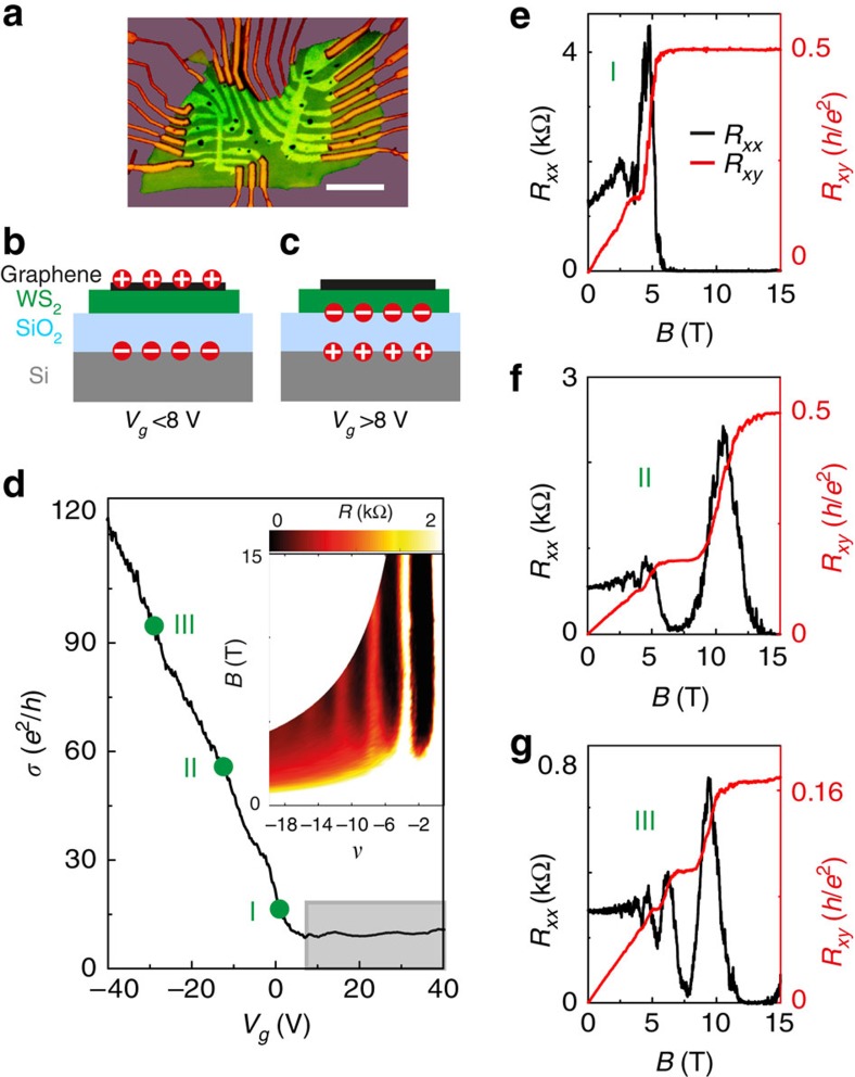
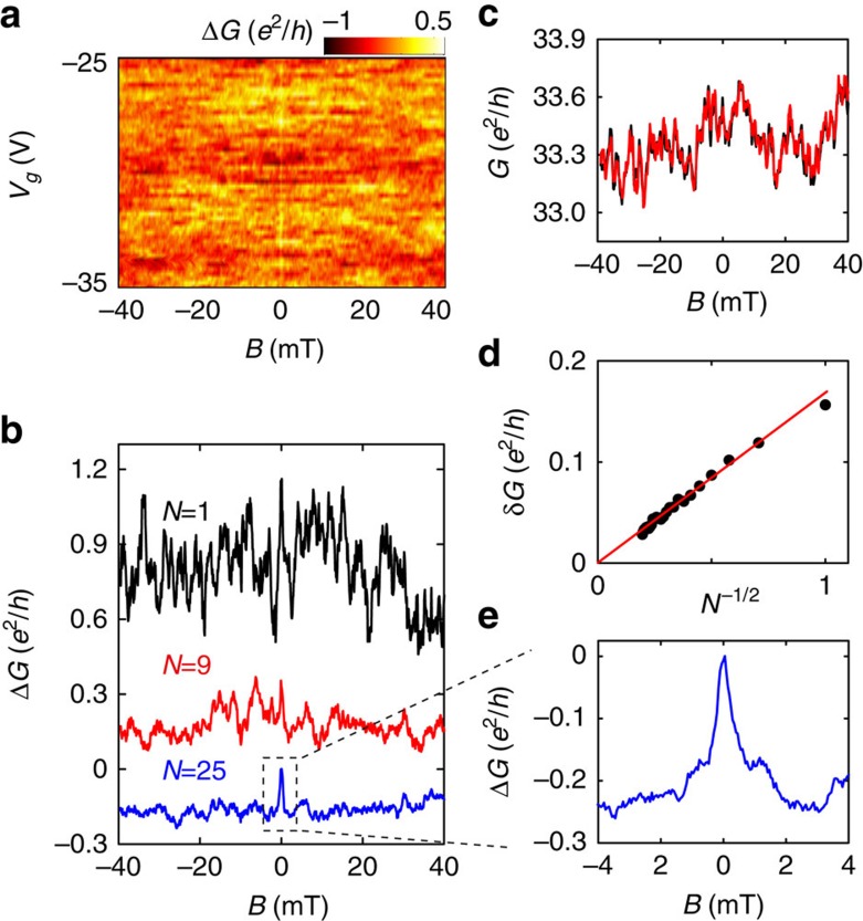
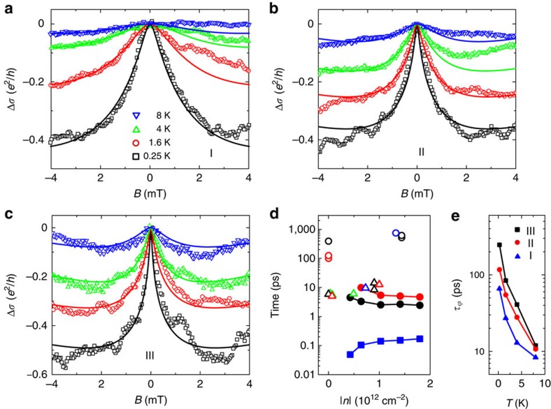
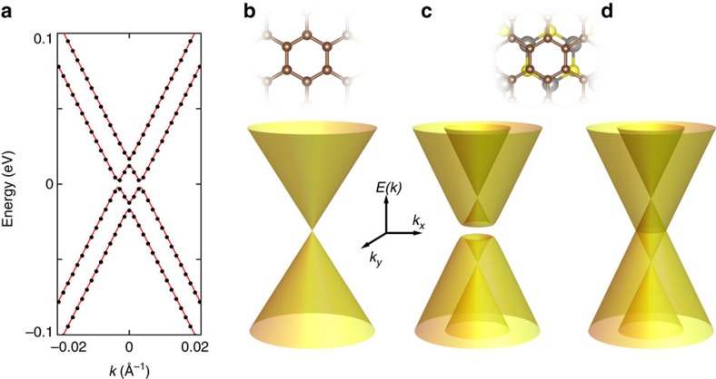
Interfacial interactions allow the electronic properties of graphene to be modified, as recently demonstrated by the appearance of satellite Dirac cones in graphene on hexagonal boron nitride substrates. Ongoing research strives to explore interfacial interactions with other materials to engineer targeted electronic properties. Here we show that with a tungsten disulfide (WS2) substrate, the strength of the spin-orbit interaction (SOI) in graphene is very strongly enhanced. The induced SOI leads to a pronounced low-temperature weak anti-localization effect and to a spin-relaxation time two to three orders of magnitude smaller than in graphene on conventional substrates. To interpret our findings we have performed first-principle electronic structure calculations, which confirm that carriers in graphene on WS2 experience a strong SOI and allow us to extract a spin-dependent low-energy effective Hamiltonian. Our analysis shows that the use of WS2 substrates opens a possible new route to access topological states of matter in graphene-based systems.


Figures

Figure 1
Figure 1. Basic electrical transport properties of graphene-on-WS2 heterostructure at 250 mK.
(a) Optical microscope image of one of our devices, with multiple contacts in a Hall-bar geometry (scale bar, 10 μm). (b,c) Schematic cross-section of the device illustrating where charge is accumulated on varying Vg below and above ∼8 V (b and c, respectively). Owing to the presence of the n-doped WS2 substrate, charges are accumulated in graphene only for Vg lower than ∼8 V (the precise value slightly varies from sample to sample, depending on the doping level of the WS2 substrate.). (d) The conductivity (σ) of the device varies linearly with Vg, below ∼8 V, and saturates for larger Vg values (shadow area). The green dots mark the ranges of Vg (I: 0–5 V; II: −10 to −15 V; and III: −25 to −30 V) used to perform ensemble averages of the device magnetoconductance. (The inset shows Shubnikov-de Hass oscillation in the longitudinal resistance Rxx originating from the half-integer quantum-Hall effect characteristic of Dirac fermions, with the black regions corresponding to Rxx minima that occur at values of filling factor |ν|=|nh/eB|=4 × (N+1/2), with N being integer) (eg) Fully developed half-integer quantum-Hall effect with vanishing Rxx (black curve) and quantized Rxy (red curve) observed at different values of Vg=0, −11.5 and −28 V (from eg) within the region I, II and III (indicated in d).
Figure 2
Figure 2. Ensemble averaging of the MC at 250 mK.
(a) Colour-coded MC, ΔG(B), as a function of Vg, with the background conductance slowly varying in Vg subtracted. The large background conductance fluctuations originating from phase-coherent interference of electron waves are apparent, and nearly completely obscure the effect of WAL around B=0 T. (b) Evolution of the averaged MC on increasing the number N of uncorrelated MC traces used to calculate the average (N=1, 9 and 25; curves offset for clarity): the conductance peak at zero B associated to WAL becomes apparent for sufficiently large values of N. (c) Two MC traces measured at Vg=−25 V (red and black curves) demonstrating the excellent reproducibility of the conductance fluctuations. (d) After averaging over N different curves, the root mean square amplitude of the conductance fluctuations (δG) decreases proportionally to N−1/2 as expected for a proper ensemble-averaging process. (e) Zoomed-in view of the ensemble-averaged MC (for N=25), which clearly exhibits a sharp conductance peak at B=0 T.
Figure 3
Figure 3. Low-temperature WAL in graphene on WS2.
(ac) Ensemble-averaged MC curves (symbols) obtained from measurements performed in different ranges of Vg (I, II and III, respectively), at several different temperatures below 8 K. The square MC Δσ=σ(B≠0)–σ(B=0) clearly exhibits a peak at zero B in all Vg ranges, whose height decreases as temperature is increased from 250 mK to 8 K, the expected behaviour of WAL due to SOI. Solid lines show the best fits to equation (1) in the main text. (d) Carrier density dependence of the relevant characteristic times. The filled squares represent the elastic scattering time (τ) estimated from the conductivity of our device at zero B; the filled black (red) circles represent the spin relaxation time (τso) extracted from the analysis of WAL (non-local spin-Hall effect). For comparison, open up-triangles represent the values of intervalley scattering time (τiv) reported in the literature, and extracted from the analysis of weak-localization measured in device similar to ours on different substrates, such as SiO2 (black and red29), hBN (green30) and GaAs (blue31). Open circles represent τso obtained from spin-valve studies on pristine graphene on SiO2 (black and red38) and hBN (blue40). (e) Temperature dependence of the phase-coherence time (τφ) of electrons in graphene-on-WS2 extracted from the analysis of WAL performed in this work, for different gate-voltage ranges. The data clearly exhibit an increase in τφ with lowering temperature.
Figure 4
Figure 4. Low-energy band structure of graphene on WS2 near the K/K′ point.
(a) Comparison of the result of the ab initio calculations with the continuum model Hamiltonian discussed in the main text. The black dots represent the low-energy dispersion relation for graphene on WS2 as obtained from our density functional theory calculations, which can be fit with excellent precision with the dispersion relation obtained from equation (2) (red lines). (bd) Evolution of the low-energy dispersion relation of graphene as a function of SOI. (b) The usual Dirac cone for spin-degenerate charge carriers in isolated graphene close to the K/K′ point. (c,d) At an interface with a WS2 substrate, the dispersion relation is modified by the effect of the induced SOI. Ab initio calculations show that the low-energy Hamiltonian in equation (2) accurately describes the modifications to the band structure of graphene. Two SOI terms, with coupling constant λ and λR, are induced by interfacial interactions. Our calculations indicate that λ∼5 meV and λR∼1 meV. With these values the dispersion relation of electrons becomes the one shown in c that, at charge neutrality, corresponds to the band structure of an insulator (with non-trivial topological properties). The size of the gap is determined by the value of λR (as long as λ>>λR). Since the gap is likely small in our devices as compared with electrostatic potential fluctuations, λR can be neglected in a first approximation, in which case the dispersion relation becomes the one shown in d.

References

    1. Kane C. L. & Mele E. J. Z(2) topological order and the quantum spin Hall effect. Phys. Rev. Lett. 95, 146802 (2005). - PubMed
    1. Kane C. L. & Mele E. J. Quantum spin Hall effect in graphene. Phys. Rev. Lett. 95, 226801 (2005). - PubMed
    1. Huertas-Hernando D., Guinea F. & Brataas A. Spin-orbit coupling in curved graphene, fullerenes, nanotubes, and nanotube caps. Phys. Rev. B 74, 155426 (2006).
    1. Min H. et al.. Intrinsic and Rashba spin-orbit interactions in graphene sheets. Phys. Rev. B 74, 165310 (2006).
    1. Konschuh S., Gmitra M. & Fabian J. Tight-binding theory of the spin-orbit coupling in graphene. Phys. Rev. B 82, 245412 (2010).

Publication types