

Wireless Power Transfer for Autonomous Wearable Neurotransmitter Sensors
- PMID: 26404311
- PMCID: PMC4610596
- DOI: 10.3390/s150924553
Wireless Power Transfer for Autonomous Wearable Neurotransmitter Sensors
Abstract
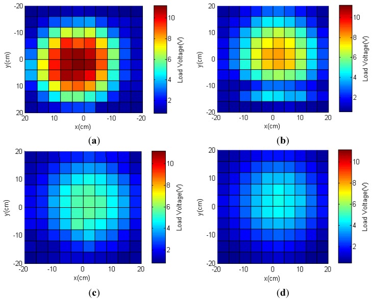
In this paper, we report a power management system for autonomous and real-time monitoring of the neurotransmitter L-glutamate (L-Glu). A low-power, low-noise, and high-gain recording module was designed to acquire signal from an implantable flexible L-Glu sensor fabricated by micro-electro-mechanical system (MEMS)-based processes. The wearable recording module was wirelessly powered through inductive coupling transmitter antennas. Lateral and angular misalignments of the receiver antennas were resolved by using a multi-transmitter antenna configuration. The effective coverage, over which the recording module functioned properly, was improved with the use of in-phase transmitter antennas. Experimental results showed that the recording system was capable of operating continuously at distances of 4 cm, 7 cm and 10 cm. The wireless power management system reduced the weight of the recording module, eliminated human intervention and enabled animal experimentation for extended durations.
Keywords: L-glutamate sensors; multi-transmitter antenna; neurotransmitter sensor recorder; wireless power transmission.
Figures


Similar articles
-
Wireless energizing system for an automated implantable sensor.Rev Sci Instrum. 2016 Jul;87(7):074708. doi: 10.1063/1.4959269. Rev Sci Instrum. 2016. PMID: 27475582
-
Energy scavenging for long-term deployable wireless sensor networks.Talanta. 2008 May 15;75(3):613-23. doi: 10.1016/j.talanta.2007.12.021. Epub 2007 Dec 26. Talanta. 2008. PMID: 18585122 Review.
-
A wireless power transmission system for implantable devices in freely moving rodents.Med Biol Eng Comput. 2014 Aug;52(8):639-51. doi: 10.1007/s11517-014-1169-3. Epub 2014 Jun 20. Med Biol Eng Comput. 2014. PMID: 24946939
-
Design and Experimental Verification of a 0.19 V 53 μW 65 nm CMOS Integrated Supply-Sensing Sensor With a Supply-Insensitive Temperature Sensor and an Inductive-Coupling Transmitter for a Self-Powered Bio-sensing System Using a Biofuel Cell.IEEE Trans Biomed Circuits Syst. 2017 Dec;11(6):1313-1323. doi: 10.1109/TBCAS.2017.2735447. IEEE Trans Biomed Circuits Syst. 2017. PMID: 29293424
-
Wireless integrated biosensors for point-of-care diagnostic applications.Sensors (Basel). 2015 Feb 2;15(2):3236-61. doi: 10.3390/s150203236. Sensors (Basel). 2015. PMID: 25648709 Free PMC article. Review.
Cited by
-
A Wideband Circularly Polarized Pixelated Dielectric Resonator Antenna.Sensors (Basel). 2016 Aug 23;16(9):1349. doi: 10.3390/s16091349. Sensors (Basel). 2016. PMID: 27563897 Free PMC article.
-
Co-Design Method and Wafer-Level Packaging Technique of Thin-Film Flexible Antenna and Silicon CMOS Rectifier Chips for Wireless-Powered Neural Interface Systems.Sensors (Basel). 2015 Dec 16;15(12):31821-32. doi: 10.3390/s151229885. Sensors (Basel). 2015. PMID: 26694407 Free PMC article.
-
Wearable bioelectronics based on emerging nanomaterials for telehealth applications.Device. 2025 Jan 17;3(1):100676. doi: 10.1016/j.device.2024.100676. Epub 2025 Jan 9. Device. 2025. PMID: 40206603 Free PMC article.
-
A Printed Wearable Dual-Band Antenna for Wireless Power Transfer.Sensors (Basel). 2019 Apr 11;19(7):1732. doi: 10.3390/s19071732. Sensors (Basel). 2019. PMID: 30978961 Free PMC article.
References
-
- Huang X., Im H., Lee D., Kim H., Choi Y. Ferrocene functionalized single-walled carbon nanotube bundles. Hybrid interdigitated construction film for L-Glutamate detection. J. Phys. Chem. C. 2007;111:1200–1206. doi: 10.1021/jp065747b. - DOI
-
- Cao H., Li A., Nguyen C.M., Peng Y., Chiao J.-C. An integrated flexible implantable micro-probe for sensing neurotransmitters. IEEE Sens. J. 2012;12:1618–1624. doi: 10.1109/JSEN.2011.2173674. - DOI
MeSH terms
Substances
LinkOut - more resources
Full Text Sources
Other Literature Sources
