. 2015 Sep 25:5:14272.
doi: 10.1038/srep14272.

Microfluidic cytometric analysis of cancer cell transportability and invasiveness

Affiliations

Microfluidic cytometric analysis of cancer cell transportability and invasiveness

Zongbin Liu et al. Sci Rep. .

Abstract

The extensive phenotypic and functional heterogeneity of cancer cells plays an important role in tumor progression and therapeutic resistance. Characterizing this heterogeneity and identifying invasive phenotype may provide possibility to improve chemotherapy treatment. By mimicking cancer cell perfusion through circulatory system in metastasis, we develop a unique microfluidic cytometry (MC) platform to separate cancer cells at high throughput, and further derive a physical parameter 'transportability' to characterize the ability to pass through micro-constrictions. The transportability is determined by cell stiffness and cell-surface frictional property, and can be used to probe tumor heterogeneity, discriminate more invasive phenotypes and correlate with biomarker expressions in breast cancer cells. Decreased cell stiffness and cell-surface frictional force leads to an increase in transportability and may be a feature of invasive cancer cells by promoting cell perfusion through narrow spaces in circulatory system. The MC-Chip provides a promising microfluidic platform for studying cell mechanics and transportability could be used as a novel marker for probing tumor heterogeneity and determining invasive phenotypes.


Figures

Figure 1
Figure 1. Device design and principle function.
(a) The schematic illustrates cell separation based on size and transportability. A deterministic lateral displacement (DLD) microarray is shown on the left and a trapping barrier microarray is shown on the right. formula image
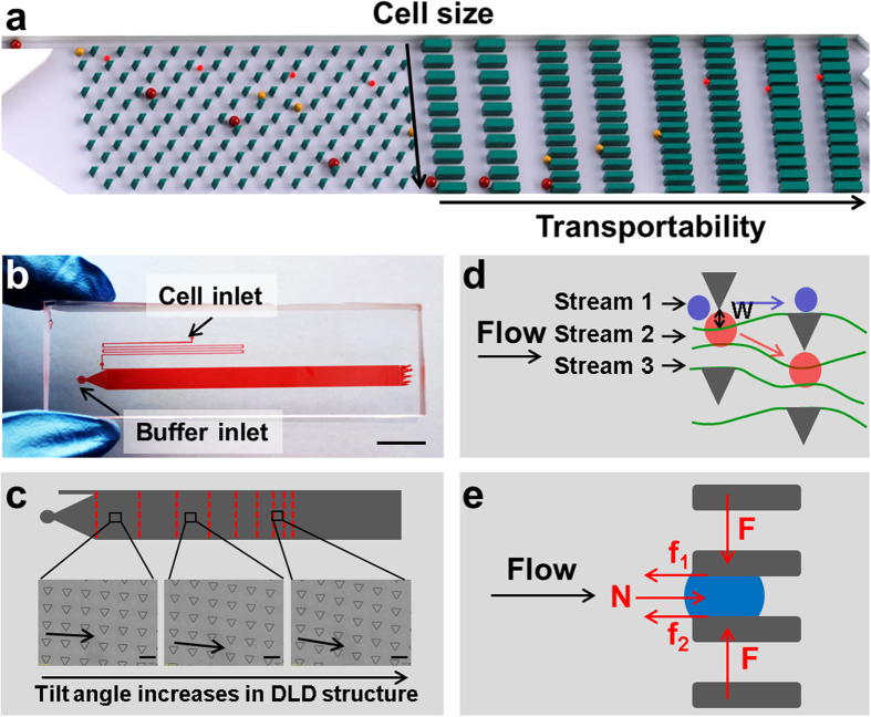
, where E is Young’s modulus and μ is friction coefficient. (b) The overview shows the cell and buffer inlets on the microfluidic device, scale bar = 1 cm. (c) DLD structure design is shown. Rows of triangular microposts with sides 30 μm in length, 27 μm in height, and separated by 30 μm gaps, are arranged with a tilt angle that gradually increases from the inlet to outlet side of the device, scale bar = 50 μm. (d) Cell size-based separation in the DLD structure is performed by dividing fluid flow into three streams using the microposts. Small cells (blue circles) follow the direction of fluid flow, whereas large cells (red circles) follow the direction of tilt of micropost rows, W = length of the first stream. (e) Stress analyses of trapped cells are performed, N = flow-induced force, arrows indicate the direction of fluid flow, F = compression force from micropost, f1 and f2 = friction forces between cell and micropost.
Figure 2
Figure 2. On-chip separation of MCF-7/GFP cells is achieved using the microfluidic device.
(a) Microscopic images of fluorescence (green) and bright-field channels are merged. Cell size increases from top to bottom in the vertical direction. Transportability has horizontal distribution. The flow rate is 10 μL/min, scale bar = 1 mm. (b) Microscopic images show the trapped cells at indicated positions in the device, scale bar = 50 μm. (c) Cell diameter versus displacement is plotted for MCF-7 cells separated in untreated and PLL-treated chips, and cytochalasin D treated MCF-7 cells. (d) The proportion of MCF-7 cells separated in untreated and PLL-treated chips, and cytochalasin D treated MCF-7 cells with indicated transportability is shown.
Figure 3
Figure 3. Transportabilities of six breast epithelial cell lines are compared.
(af) Transportability versus cell diameter is plotted in MCF-10A (a), MCF-7 (b), SK-BR-3 (c), MDA-MB-231 (d), SUM 159 (e), and SUM 149 (f) breast cancer cell lines. The blue lines in (d) indicate the linear-like distribution of transportability and cell diameter. Top blue line shows transportability of cells trapped at smaller gap, while bottom blue line shows transportability of cells trapped at larger gap. Inner and outer red circles indicate the 50% and 90% confidence interval centered at the mean depicted by a green dot, N = number of cells counted. (g) The average transportability of the six breast cancer cell lines. Data are presented as mean ± s.d. ***P < 0.001. (h) The average cell diameter of the six breast cancer cell lines. Data are presented as mean ± s.d.
Figure 4
Figure 4. Transportability and biological parameters of untreated and TPA-induced MCF-7 cells are compared.
(a) A plot of cell diameter distribution versus displacement shows linear correlation of these parameters for MCF-7 and TPA-induced MCF-7 cells. (b) Transportability versus cell diameter is plotted for MCF-7 and TPA-induced MCF-7 cells. Red and blue circles indicate the 80% confidence interval centered at the mean depicted by a green dot. The counts of MCF-7 and MCF-7/TPA are 947 and 1426 respectively. (c) Young’s moduli, determined by atomic force microscopy (AFM), and transportability are compared. Data are presented as mean ± s.d. ***P < 0.001 compared to MCF-7 cells. (d) Immunofluorescence staining of indicated proteins and counterstaining with DAPI were performed in MCF-7 and TPA-induced MCF-7 cells, scale bar = 20 μm. (e) Western blot analysis (cropped images) in MCF-7 and TPA-induced MCF-7 cells reveal that N-cadherin and snail are slightly up-regulated and F-actin, keratin 18, E-cadherin and vinculin are slightly down-regulated in TPA-induced MCF-7 cells. All western blot experiments were run under the same experimental conditions. Full-length blots are presented in Supplementary Figure S7.
Figure 5
Figure 5. The relationship between CD24/CD44 expression and transportability in SUM149 cells is investigated.
(a) Immunofluorescence staining is shown for CD24 (green), CD44 (red), and the merged image. The cells labeled 1 and 7 are CD24High/CD44Low phenotypes. The cells labeled 2, 5, and 6 are CD24Low/CD44High phenotypes. The cell labeled 4 is CD24High/CD44High phenotype. The cell labeled 3 is CD24Low/CD44Low phenotype, scale bar = 50 μm. (b) Microscopic images show CD24 and CD44 staining of trapped cells of indicated diameters and transportability, scale bar = 100 μm. (c) The proportion of CD24High cells is plotted versus gap width. The proportion of cells expressing CD24 decreases with transportability. (d) The proportion of CD44High cells is plotted versus gap width. The proportion of cells expressing CD44 increases with transportability. (e) The proportion of CD24Low/CD44High cells is plotted versus gap width. The proportion of cells with phenotype CD24Low/CD44High increases with transportability. (f) Transportability versus cell diameter is plotted for CD24Low/CD44High cells and SUM 149. Blue and black circles indicate the 80% confidence interval centered at the mean depicted by a green dot.
Figure 6
Figure 6. Transportability and biological parameters of tumor cells dissociated from the tumor center and periphery are compared.
(a) Images show the excised tumor, tumor center, and tumor periphery. (b) Fluorescence images show E-cadherin (green) and vimentin (red) staining of cells from the tumor center and periphery. Cells were counterstained with DAPI. E-cadherin is down-regulated and vimentin is up-regulated in cells from tumor periphery, scale bar = 20 μm. (c,d) Transportability is plotted versus cell diameter for cells from the tumor center (c) and tumor periphery (d). Inner and outer red circles indicate the 50% and 90% confidence interval centered at the mean depicted by a green dot, N = number of cells counted. (e) The proportion of indicated cell types with indicated levels of transportability is given. The tumor periphery contains more cells with high transportability. (f) A comparison of Young’s moduli and transportability is made in indicated cells. Cells from the tumor periphery are more flexible and have higher transportability than MCF-7 cells and cells from the tumor center. Data are presented as mean ± s.d. ***P < 0.001 compared to tumor center cells.

References

    1. Thiery J. P. & Lim C. T. Tumor dissemination: an EMT affair. Cancer Cell 23, 272–273 (2013). - PubMed
    1. Yilmaz M. & Christofori G. EMT, the cytoskeleton, and cancer cell invasion. Cancer Metast. Rev. 28, 15–33 (2009). - PubMed
    1. Chaffer C. L. & Weinberg R. A. A perspective on cancer cell metastasis. Science 331, 1559–1564 (2011). - PubMed
    1. Wirtz D., Konstantopoulos K. & Searson P. C. The physics of cancer: the role of physical interactions and mechanical forces in metastasis. Nat. Rev. Cancer 11, 512–522 (2011). - PMC - PubMed
    1. Di Carlo D. A mechanical biomarker of cell state in medicine. J. Lab. Autom. 17, 32–42 (2012). - PubMed

Publication types