. 2015 Oct 1;9(5):054118.
doi: 10.1063/1.4932303. eCollection 2015 Sep.

Automatic sequential fluid handling with multilayer microfluidic sample isolated pumping

Affiliations

Automatic sequential fluid handling with multilayer microfluidic sample isolated pumping

Jixiao Liu et al. Biomicrofluidics. .

Abstract

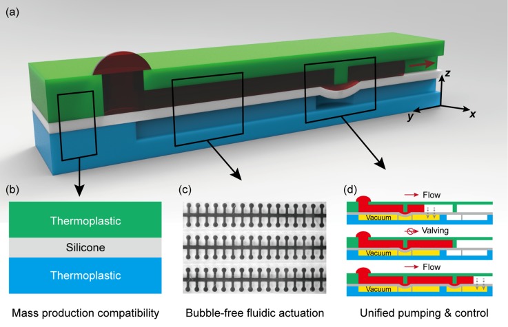
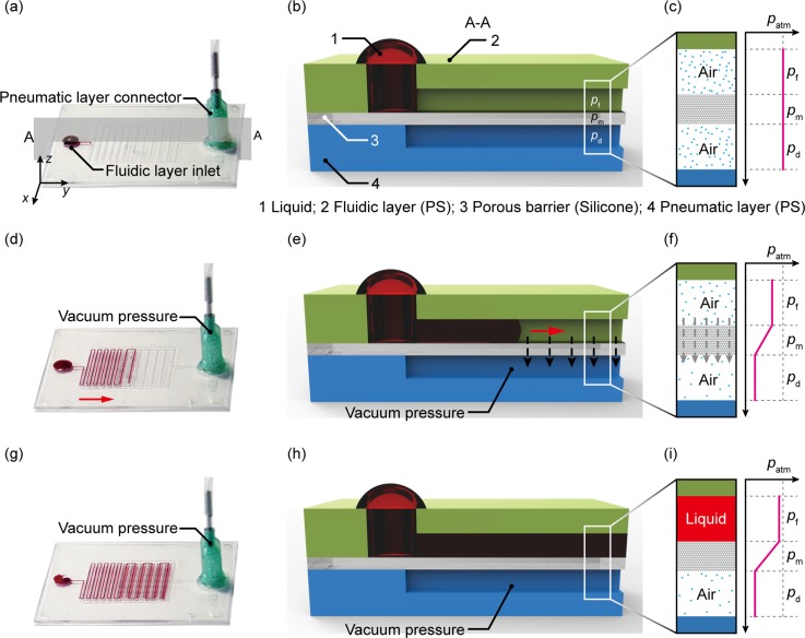
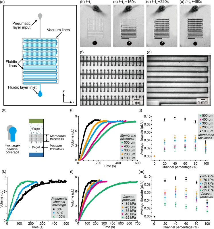
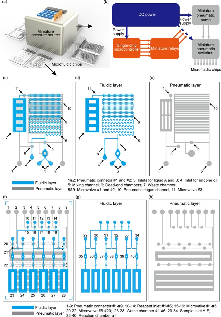
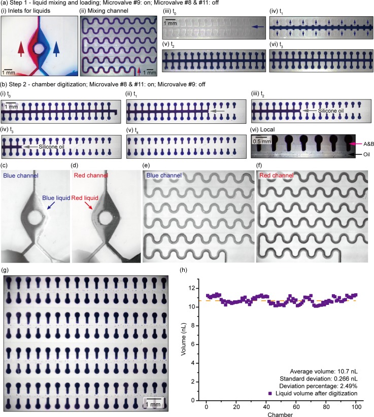
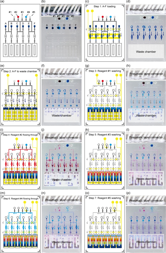
To sequentially handle fluids is of great significance in quantitative biology, analytical chemistry, and bioassays. However, the technological options are limited when building such microfluidic sequential processing systems, and one of the encountered challenges is the need for reliable, efficient, and mass-production available microfluidic pumping methods. Herein, we present a bubble-free and pumping-control unified liquid handling method that is compatible with large-scale manufacture, termed multilayer microfluidic sample isolated pumping (mμSIP). The core part of the mμSIP is the selective permeable membrane that isolates the fluidic layer from the pneumatic layer. The air diffusion from the fluidic channel network into the degassing pneumatic channel network leads to fluidic channel pressure variation, which further results in consistent bubble-free liquid pumping into the channels and the dead-end chambers. We characterize the mμSIP by comparing the fluidic actuation processes with different parameters and a flow rate range of 0.013 μl/s to 0.097 μl/s is observed in the experiments. As the proof of concept, we demonstrate an automatic sequential fluid handling system aiming at digital assays and immunoassays, which further proves the unified pumping-control and suggests that the mμSIP is suitable for functional microfluidic assays with minimal operations. We believe that the mμSIP technology and demonstrated automatic sequential fluid handling system would enrich the microfluidic toolbox and benefit further inventions.


Figures

FIG. 1.
FIG. 1.
Multilayer microfluidic sample isolated pumping (mμSIP). (a) and (b) The mμSIP device is made of thermoplastic and a silicone membrane, which makes it feasible for industrial large-scale production. (c) The mμSIP provides efficient and bubble-free liquid pumping for microfluidic assays and it is feasible for dead-end structure loading. (d) The mμSIP fluidic actuation is driven by vacuum pressure in the pneumatic layer, so by introducing pneumatic diaphragm microvalves into the structure, liquid pumping and flow control could be achieved at the same time in the device without extra accessory equipment.
FIG. 2.
FIG. 2.
The working principle of the multilayer microfluidic sample isolated pumping (mμSIP). (a) A device driven by mμSIP. Red liquid is pipetted into fluidic inlet. There is no outlet in the fluidic channel. (b) Cross-sectional view of part of the device. No vacuum is connected to the pneumatic channel, and no air diffusion or liquid flowing occurs. (c) Pressure conditions across the fluidic-membrane-pneumatic structure. Fluidic channel pressure pf, pressure on the air-permeable membrane pm, and the pneumatic channel pd are equal to the atmospheric pressure. (d) and (e) Liquid starts to flow into the fluidic channel when vacuum is activated in pneumatic channels. Vacuum in the pneumatic lines leads to air diffusion from fluidic channel through the air-permeable membrane (dotted line arrows). The liquid cannot pass through the silicone membrane. The consistent air diffusion causes fluidic channel pressure reduction, which further drives liquid to flow into the channel. (f) Both of the fluidic channel pressure pf and the pneumatic channel pressure pd are below the atmospheric pressure. The pressure difference between the pf and the pd leads to the consistent air diffusion. (g), (h), (i) The fluidic channel is filled with the liquid. Air diffusion in the filled fluidic channel section is neglected.
FIG. 3.
FIG. 3.
Experimental characterizations of the mμSIP. (a) The basic chip design. Light-blue represents fluidic channels and chambers, and light-gray represents pneumatic lines. Three layers of structures are comprised in the device. (b)–(e) Liquid sample loading under −85 kPa in the pneumatic lines. No air bubbles observed. (f) and (g) Microscopic picture of dead-end chambers and channels after pumping. (h) Major parameters considered in the characterizations: the pneumatic channel coverage, the silicone membrane thickness, and the vacuum pressure. (i) and (j) Liquid pumping curves and average flow rate with different silicone membrane thickness under vacuum pressure of −85 kPa and with 100% pneumatic channel coverage. (k) Liquid pumping with different pneumatic channel coverage under vacuum pressure of −85 kPa and with 100 μm-thick silicone membrane. (l) and (m) Liquid pumping curves and average flow rate with different vacuum pressure with 100% pneumatic channel coverage and 100 μm-thick silicone membrane. Each test condition was repeated with three devices, only average data are plotted in the (i), (k), and (l). Unless stated otherwise, the 100 μm-thick silicone membranes, the vacuum pressure of −85 kPa (with respect to the atmospheric pressure), and 100% pneumatic channel coverage are applied in the tests.
FIG. 4.
FIG. 4.
The automatic microfluidic sequential handling system. (a) The schematics of the automatic microfluidic sequential handling system: the miniature pressure source and the microfluidic chips. (b) The design of the miniature pressure source. It consists of a DC power module, a control module, and a pneumatic module. (c) The design of the two-step sequential handling device for digital assays. (d) The fluidic layer pattern. (e) The pneumatic layer patter. (f) The design of the multiple-step sequential handling device for immunoassays. (g) The fluidic layer pattern. (h) The pneumatic layer patter.
FIG. 5.
FIG. 5.
Experimental test and evaluation of the two-step sequential handling device. (a) Liquid mixing and dead-end chambers loading. The first pneumatic line is exerted with vacuum pressure. (i) Liquids A and B are loaded into the channel at the same time. (ii) Liquids are mixed in the serpentine curved channel and the solution turns to dark blue-purplish at the end of the channel. (iii) and (iv) The dead-end chambers start to load the mixed solution. (v) and (vi) Air is evacuated from the chambers and all the dead-end chambers are fully loaded at the end. (b) Chamber digitization. The second pneumatic line is switched on. The silicone oil flows into the channel to separate the chambers to accomplish digitization. The chambers are sealed with the silicone oil and cannot contact with each other during further operations. (c) and (d) Blue and red intensities at the inlet that are analyzed by Adobe Photoshop. Brighter area in the color channel represents more concentrated liquids of that color. (e) and (f) Blue and red intensities in the serpentine mixing channel that are analyzed by Adobe Photoshop. Both color intensities become uniform in the latter section of the mixing channel, which indicates the uniform mixing. (g) Chambers after fully digitalization. (h) Measurement of liquid volume in one hundred digitized chambers. Deviations of liquid volume among chambers are minor compared to the average value (see details in supplementary material).
FIG. 6.
FIG. 6.
Experimental tests of multiple step liquid sequential handling device. The device could automatically handle six samples and five reagents in seven steps. (a), (c), (e), (g), (i), (k), (m), (o) The schematics of the sequential handling procedure in each step. (b), (d), (f), (h), (J), (l), (n), (p) The experimental picture taken during the operation (chamber loadings, flowing “reactions,” and washings). Reaction chamber color changing infers reaction/mixture between the dye molecules in the samples/reagents.

Similar articles

References

    1. Volpatti L. R. and Yetisen A. K., Trends Biotechnol. 32(7), 347–350 (2014).10.1016/j.tibtech.2014.04.010 - DOI - PubMed
    1. Unger M. A., Chou H. P., Thorsen T., Scherer A., and Quake S. R., Science 288(5463), 113–116 (2000).10.1126/science.288.5463.113 - DOI - PubMed
    1. Thorsen T., Maerkl S. J., and Quake S. R., Science 298(5593), 580–584 (2002).10.1126/science.1076996 - DOI - PubMed
    1. Wheeler T. D. and Stroock A. D., Nature 455(7210), 208–212 (2008).10.1038/nature07226 - DOI - PubMed
    1. Yu X., Hartmann M., Wang Q., Poetz O., Schneiderhan-Marra N., Stoll D., Kazmaier C., and Joos T. O., PLos One 5(10), e13125 (2010).10.1371/journal.pone.0013125 - DOI - PMC - PubMed

LinkOut - more resources