One-step large-scale deposition of salt-free DNA origami nanostructures
- PMID: 26492833
- PMCID: PMC4616047
- DOI: 10.1038/srep15634
One-step large-scale deposition of salt-free DNA origami nanostructures
Abstract
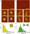
DNA origami nanostructures have tremendous potential to serve as versatile platforms in self-assembly -based nanofabrication and in highly parallel nanoscale patterning. However, uniform deposition and reliable anchoring of DNA nanostructures often requires specific conditions, such as pre-treatment of the chosen substrate or a fine-tuned salt concentration for the deposition buffer. In addition, currently available deposition techniques are suitable merely for small scales. In this article, we exploit a spray-coating technique in order to resolve the aforementioned issues in the deposition of different 2D and 3D DNA origami nanostructures. We show that purified DNA origamis can be controllably deposited on silicon and glass substrates by the proposed method. The results are verified using either atomic force microscopy or fluorescence microscopy depending on the shape of the DNA origami. DNA origamis are successfully deposited onto untreated substrates with surface coverage of about 4 objects/mm(2). Further, the DNA nanostructures maintain their shape even if the salt residues are removed from the DNA origami fabrication buffer after the folding procedure. We believe that the presented one-step spray-coating method will find use in various fields of material sciences, especially in the development of DNA biochips and in the fabrication of metamaterials and plasmonic devices through DNA metallisation.
Figures


Similar articles
-
Dielectrophoretic trapping of multilayer DNA origami nanostructures and DNA origami-induced local destruction of silicon dioxide.Electrophoresis. 2015 Jan;36(2):255-62. doi: 10.1002/elps.201400323. Epub 2014 Oct 27. Electrophoresis. 2015. PMID: 25225147
-
Surface-Assisted Assembly of DNA Origami Lattices on Silicon Wafers.Methods Mol Biol. 2025;2901:89-101. doi: 10.1007/978-1-0716-4394-5_7. Methods Mol Biol. 2025. PMID: 40175869
-
Custom-shaped metal nanostructures based on DNA origami silhouettes.Nanoscale. 2015 Jul 14;7(26):11267-72. doi: 10.1039/c5nr02300a. Nanoscale. 2015. PMID: 26066528
-
Surface Assembly of DNA Origami on a Lipid Bilayer Observed Using High-Speed Atomic Force Microscopy.Molecules. 2022 Jun 30;27(13):4224. doi: 10.3390/molecules27134224. Molecules. 2022. PMID: 35807467 Free PMC article. Review.
-
Recent Developments of New DNA Origami Nanostructures for Drug Delivery.Curr Pharm Des. 2015;21(22):3181-90. doi: 10.2174/1381612821666150531165551. Curr Pharm Des. 2015. PMID: 26027568 Review.
Cited by
-
Nanometrology and super-resolution imaging with DNA.MRS Bull. 2017 Dec;42(12):951-959. doi: 10.1557/mrs.2017.274. Epub 2017 Dec 8. MRS Bull. 2017. PMID: 31485100 Free PMC article.
-
Structural stability of DNA origami nanostructures under application-specific conditions.Comput Struct Biotechnol J. 2018 Sep 18;16:342-349. doi: 10.1016/j.csbj.2018.09.002. eCollection 2018. Comput Struct Biotechnol J. 2018. PMID: 30305885 Free PMC article. Review.
-
Time-Dependent DNA Origami Denaturation by Guanidinium Chloride, Guanidinium Sulfate, and Guanidinium Thiocyanate.Int J Mol Sci. 2022 Aug 1;23(15):8547. doi: 10.3390/ijms23158547. Int J Mol Sci. 2022. PMID: 35955680 Free PMC article.
-
Fluorescence Anisotropy for Detailed Analysis of Doxorubicin Loading into DNA Origami Nanocarriers for Drug Delivery.ACS Appl Nano Mater. 2025 Jun 24;8(26):13274-13284. doi: 10.1021/acsanm.5c01518. eCollection 2025 Jul 4. ACS Appl Nano Mater. 2025. PMID: 40636881 Free PMC article.
-
Cationic Albumin Encapsulated DNA Origami for Enhanced Cellular Transfection and Stability.Materials (Basel). 2019 Mar 21;12(6):949. doi: 10.3390/ma12060949. Materials (Basel). 2019. PMID: 30901888 Free PMC article.
References
Publication types
MeSH terms
Substances
LinkOut - more resources
Full Text Sources
Other Literature Sources

