. 2015 Dec;6(6):601-10.
doi: 10.1007/s13244-015-0442-9. Epub 2015 Oct 22.

A practical guide for performing arthrography under fluoroscopic or ultrasound guidance

Affiliations

A practical guide for performing arthrography under fluoroscopic or ultrasound guidance

Eugen Lungu et al. Insights Imaging. 2015 Dec.

Abstract

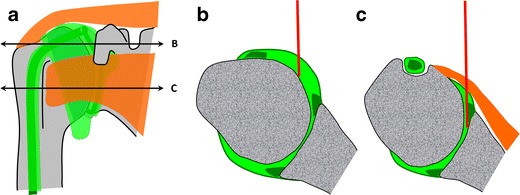
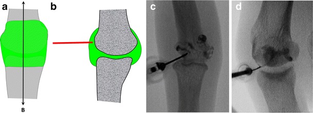
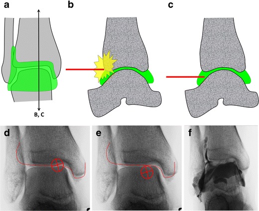
We propose a practical approach for performing arthrography with fluoroscopic or ultrasound guidance. Different approaches to the principal joints of the upper limb (shoulder, elbow, wrist and fingers), lower limb (hip, knee, ankle and foot) as well as the facet joints of the spine are discussed and illustrated with numerous drawings. Whenever possible, we emphasise the concept of targeting articular recesses, which offers many advantages over traditional techniques aiming at the joint space.

Teaching points: • Arthrography remains a foremost technique in musculoskeletal radiology • Most joints can be successfully accessed by targeting the articular recess • Targeting the recess offers several advantages over traditional approaches • Ultrasound-guidance is now favoured over fluoroscopy and targeting the recess is equally applicable.

Keywords: Arthrography; Articular recess; Fluoroscopy; Intra-articular injection; Ultrasound.


Figures

Fig. 1
Fig. 1
Commonly encountered difficulties with direct puncture of the radiological joint space. Direct access to the radiological joint space (a) may be impaired by the normal anatomy (spheroid and condyloid joints) (b) and could require repositioning of the limb that may, at times, be challenging (c). Degenerative changes such as joint space narrowing and osteophytes may also hinder a direct approach (d)
Fig. 2
Fig. 2
Targeting the articular recess rather than the radiological joint space on an anteroposterior radiograph (a) and its corresponding sagittal anatomical diagram (b). This approach can alleviate the difficulties mentioned previously
Fig. 3
Fig. 3
Glenohumeral joint injection by targeting the rotator interval. a The rotator interval (*) is limited superiorly by the supraspinatus tendon (SS), anteriorly by the subscapularis tendon (sSc) and contains the long head of the biceps tendon (LB). b The target is the upper medial quadrant of the humeral head. c and d Insertion of the needle until bone contact and confirmation of adequate position by opacification of the joint space and of the subscapularis recess
Fig. 4
Fig. 4
a Comparison of the rotator interval approach to the Schneider technique on a diagrammatic representation of the shoulder joint, with two transverse sections (B and C). b At the level of the rotator interval, the needle path is shorter and the long head of the biceps tendon is easily avoided by placing the arm in external rotation. c With the Schneider technique, the subscapularis tendon and antero-inferior labrum are regularly perforated by the needle or impregnated by the contrast agent
Fig. 5
Fig. 5
Representation of the elbow joint depicting elbow arthrography. a The needle is inserted in the anterior aspect of the humeroradial compartment by passing through the capsule. b Confirmation of adequate position by opacification of the anterior and posterior recesses
Fig. 6
Fig. 6
Representation of the wrist joint (a) with sagittal (B) and transverse (C) sections. The posterior radius overlies both radiocarpal (b) and distal radioulnar (c) joint spaces, precluding direct approaches
Fig. 7
Fig. 7
Radiocarpal joint injection by targeting the posterior radioscaphoid recess. a The target is the mid portion of the scaphoid. b The needle is angled proximally until bone contact. c Confirmation of adequate position by opacification of the radioscaphoid recess
Fig. 8
Fig. 8
Distal radioulnar joint injection by targeting the posterior radioulnar recess. a The target is the distal and lateral aspect of the ulnar head. b The needle is inserted in a straight direction until bone contact. c Confirmation of adequate position by opacification of the radioulnar compartment
Fig. 9
Fig. 9
Diagrammatic representation of a metacarpophalanngeal joint (a) with corresponding sagittal section (b) showing that the articular recess is more developed on the dorsal aspect of the metacarpal head and can be easily punctured. Interphalangeal (c) and metatarsophalangeal (d) arthrographies are performed by using the same principle
Fig. 10
Fig. 10
Ultrasound-guided aspiration of the first metatarsophalangeal joint. a Longitudinal view demonstrating distension of the dorsal recess by joint effusion. Note that the dorsal recess extends proximally on the dorsum of the first metacarpal. b Transverse view demonstrating the insertion of the needle in the dorsal recess and fluid aspiration
Fig. 11
Fig. 11
Diagrammatic representation of the hip joint (a) with transverse oblique sections (B, C). Both the lateral (b) and medial (c) portions separated by the zona orbicularis (*) can be targeted for hip injections
Fig. 12
Fig. 12
Hip joint injection by targeting the lateral portion. a The target is the lateral aspect of the femoral neck. b The needle is inserted until bone contact and opacification of the joint space confirms the adequate position
Fig. 13
Fig. 13
Hip joint injection by targeting the medial portion. a The target is the superior aspect of the head-neck junction away from the femoral vessels. b The needle is inserted upon bone contact and opacification of the joint space confirms the adequate position
Fig. 14
Fig. 14
Anterior approach targeting the lateral femoral condyle as shown on a diagrammatic representation of the knee joint (a) with a transverse section through the femoral condyles (b). c The target is the anterior and lower aspect of the lateral femoral condyle. d The needle is inserted until bone contact and adequate position is confirmed by opacification of the joint space
Fig. 15
Fig. 15
Diagrammatic representation of the ankle joint (a) with sagittal sections (b, c). There is a risk of hitting the anterior tibial margin (red dotted line) if the radiological joint space is targeted on an anteroposterior view (d). The anterior recess can be targeted just below the radiological joint space (e). After needle insertion, the adequate position is confirmed by opacification of the joint space (f)
Fig. 16
Fig. 16
Diagrammatic representation of the cervical facet joints (a) with transverse (B) and sagittal sections (C). A lateral approach as represented in blue (b, c) may lead to perforation of major vessels and dura or nerve root sheaths. A posterior approach targeting the inferior recess as represented in red (a, b) may be safer because all major neurovascular structures are protected by the articular pillar. The needle is inserted until bone contact and the adequate position is confirmed by opacification of the joint space (d)
Fig. 17
Fig. 17
a Diagrammatic representation of the lumbar facet joints with transverse (B) and sagittal sections (C). b The classical posterolateral approach represented in blue can be impeded by the curved orientation and degenerative changes of the joint. c A posterior approach targeting the inferior recess may be an easier alternative. d The inferior recess can be enlarged by placing a pillow under the patient’s abdomen in order to reduce the physiological lordosis. e The target is the medial and inferior aspect of the pedicle projection (indicated by yellow circles at L5). f The needle is inserted until bone contact and the adequate position is confirmed by opacification of the joint space. g Oblique views are not required with this approach and are only displayed here for a better understanding of the anatomy
Fig. 18
Fig. 18
a, b This example of knee arthrography illustrates minimal pooling of contrast medium around the needle tip (arrow) reflecting mixed injection (intra-articular and extra-articular). c Mixed injection may occur when a shallow recess is approached perpendicularly with a long-bevelled needle. Better to use a short-bevelled needle (d) or to direct the needle tangentially to the cartilage (e)

Similar articles

Cited by

References

    1. Bonakdarpour A, Reinus WR, Khurana JS (2010) Diagnostic imaging of musculoskeletal diseases: a systematic approach. Springer, New York
    1. Peterson JJ, Bancroft LW. History of arthrography. Radiol Clin N Am. 2009;47:373–386. doi: 10.1016/j.rcl.2008.12.001. - DOI - PubMed
    1. Hodler J. Technical errors in MR arthrography. Skelet Radiol. 2008;37:9–18. doi: 10.1007/s00256-007-0329-z. - DOI - PubMed
    1. Ng AW, Hung EH, Griffith JF, Tong CS, Cho CC. Comparison of ultrasound versus fluorcoscopic guided rotator cuff interval approach for MR arthrography. Clin Imaging. 2013;37:548–553. doi: 10.1016/j.clinimag.2012.08.002. - DOI - PubMed
    1. Rutten MJ, Collins JM, Maresch BJ, Smeets JH, Janssen CM, Kiemeney LA, et al. Glenohumeral joint injection: a comparative study of ultrasound and fluoroscopically guided techniques before MR arthrography. Eur Radiol. 2009;19:722–730. doi: 10.1007/s00330-008-1200-x. - DOI - PMC - PubMed

LinkOut - more resources