Review
. 2016 Apr 1:34:60-72.
doi: 10.1016/j.actbio.2015.10.030. Epub 2015 Oct 20.

Polymer microarray technology for stem cell engineering

Affiliations
Review

Polymer microarray technology for stem cell engineering

Robert Coyle et al. Acta Biomater. .

Abstract

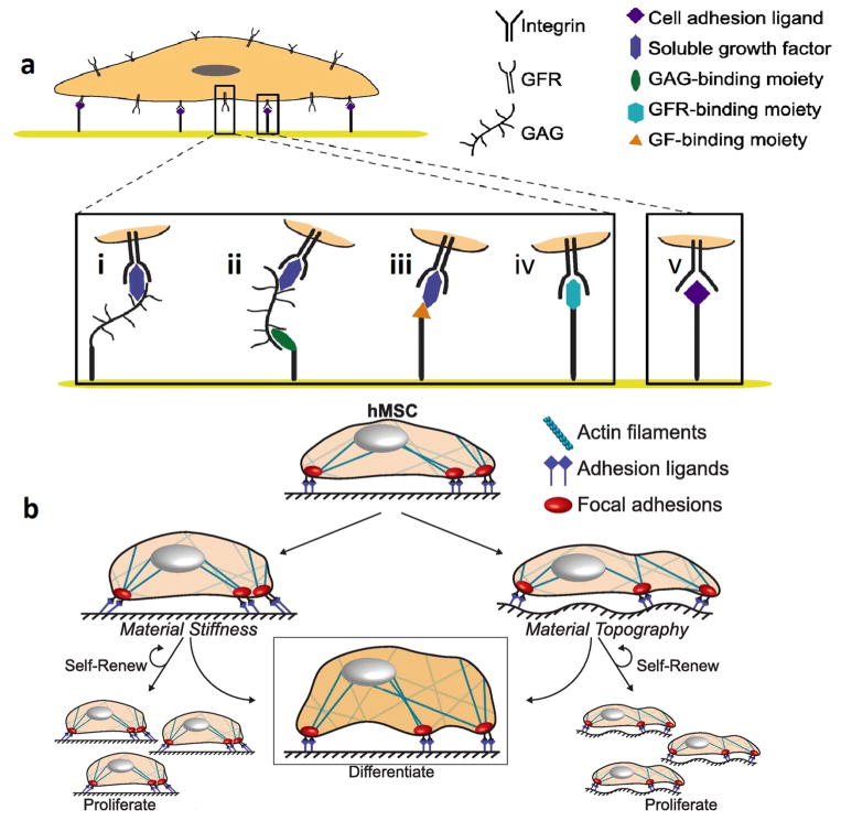
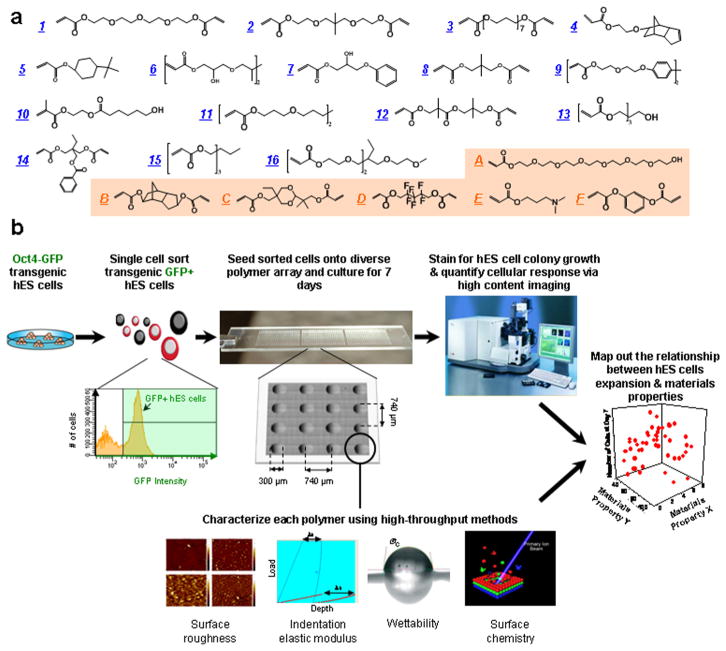
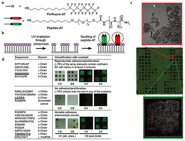
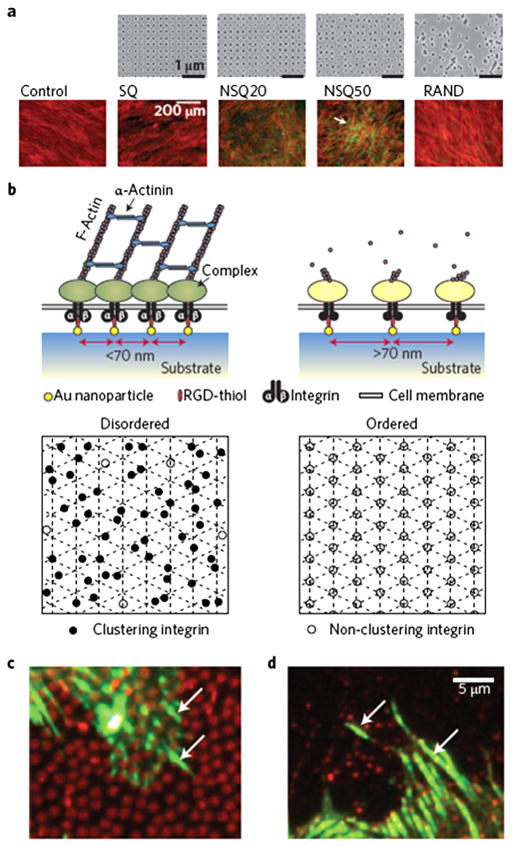
Stem cells hold remarkable promise for applications in tissue engineering and disease modeling. During the past decade, significant progress has been made in developing soluble factors (e.g., small molecules and growth factors) to direct stem cells into a desired phenotype. However, the current lack of suitable synthetic materials to regulate stem cell activity has limited the realization of the enormous potential of stem cells. This can be attributed to a large number of materials properties (e.g., chemical structures and physical properties of materials) that can affect stem cell fate. This makes it challenging to design biomaterials to direct stem cell behavior. To address this, polymer microarray technology has been developed to rapidly identify materials for a variety of stem cell applications. In this article, we summarize recent developments in polymer array technology and their applications in stem cell engineering.

Statement of significance: Stem cells hold remarkable promise for applications in tissue engineering and disease modeling. In the last decade, significant progress has been made in developing chemically defined media to direct stem cells into a desired phenotype. However, the current lack of the suitable synthetic materials to regulate stem cell activities has been limiting the realization of the potential of stem cells. This can be attributed to the number of variables in material properties (e.g., chemical structures and physical properties) that can affect stem cells. Polymer microarray technology has shown to be a powerful tool to rapidly identify materials for a variety of stem cell applications. Here we summarize recent developments in polymer array technology and their applications in stem cell engineering.

Keywords: Elastic modulus; Polymer microarray; Stem cell; Surface chemistry; Surface topography.


Figures

Fig. 1
Fig. 1
Stem cell interactions with chemical and physical cues. (a) Chemical interactions on materials can regulate growth factor signaling. Engineered materials may incorporate (i) covalently bound glycosaminoglycans (GAGs) or proteoglycans (PGs) or (ii) moieties that bind GAGs/PGs, which can in turn sequester growth factors from the stem cell microenvironment. Alternatively, materials may be functionalized with (iii) moieties that bind growth factors or (iv) moieties that directly interact with growth factor receptors (GFRs), to upregulate or downregulate GFR signaling. Finally, GFRs and their associated signaling pathways may synergize with (v) integrin-mediated adhesion and signaling downstream of adhesion. (b) Mechanical properties of the microenvironment. Resistance to deformation on stiff materials increases cytoskeletal tension of human mesenchymal stem cells (hMSC) through focal adhesion kinase (FAK) and Rho-associated kinase (ROCK) activity, leading to differentiation. (left) Introduction of topography results in rearrangement of integrins at the cell–material interface, promoting topography-dependent hMSC proliferation, self-renewal, or differentiation. (right) (Figure from Ref. [30] with permission).
Fig. 2
Fig. 2
High-throughput screening of biomaterials for clonal growth. (a) Monomers used for array synthesis were classified into two categories: “major” monomers that constitute >50% of the reactant mixture and “minor” monomers that constitute <50% of the mixture. Sixteen major monomers were named numerically (blue), and six minor monomers were labeled alphabetically (orange). (b) Schematic diagram of the screen. First, transgenic Oct4-GFP hES cells were maintained on mEFs. Then flow cytometry enabled the isolation of high purity undifferentiated hES cells from the completely dissociated coculture of hES cells and mEFs. A flow cytometry histogram during a representative cell sort is shown. GFP + cells (right of the black gate) were seeded onto the arrays, whereas the differentiated cells and mEFs (GFP−, left of the black gate) were not used. A photograph of the polymer microarray with 16 polymer spots is shown to illustrate dimensions and separation. Each polymer was also characterized using high-throughput methods to characterize its surface roughness, indentation elastic modulus, wettability (water contact angle, °C) and surface chemistry. Finally, the cellular response on the polymer array was quantified using laser-scanning cytometry, and structure–function relationships were determined by numerical analysis of both the cellular response and materials characterization data. (Figure from Ref. [54] with permission). (For interpretation of the references to color in this figure legend, the reader is referred to the web version of this article.)
Fig. 3
Fig. 3
SAM surface array screen for ES cell growth and self-renewal. (a) Structure of alkanethiols used for the assembly of the array. “R” denotes amino acid side chains. (b) A two-step process was used to generate the arrays. A uniform SAM composed of perfluoro-AT was photopatterned and solutions of peptide-ATs were spotted onto the exposed gold areas to form peptide-terminated SAM array elements. (c) A representative array containing 18 different peptide-ATs was screened to identify surfaces that promote proliferation of ES cell line H9. The peptide-displaying SAMs are arranged in a mirror-symmetric pattern (bottom and top halves of chip have identical array elements). Each half of the array contains 18 laminin-derived peptide-ATs spotted in groups of four (2 × 2 elements) arranged in a left-to-right horizontal comb pattern. The remaining array elements are filled with nonadhesive glucamine-AT. The array was incubated with media containing 20% FBS and thoroughly washed with serum-free media. Cells were grown on the array for 6 d in culture media, fixed, and stained for alkaline phosphatase (AP). The positions of cell growth are symmetric and emphasize the reproducibility of ES cell responses to the array elements. The array was mounted onto a glass slide and scanned using a flatbed scanner. The phase-contrast 10× images reveal morphological differences between AP-positive undifferentiated (left) and AP-negative differentiated ES cells (right). Array dimensions: 22 × 22 mm; each element is 0.8 mm. (d) Summary of results from multiple screens for 18 laminin-derived peptides and ES cell lines H1 and H9. Laminin chain origin is shown for each peptide. Following 5–7 d of growth, substrates were categorized according to their ability to accommodate confluent (square-shaped) and undifferentiated colonies, as judged by staining for alkaline phosphatase (purple) or Oct4 (green). Each synthetic substrate was tested four to eight times in each screen; therefore, the fraction of array elements presenting square ES cell colonies serves as a convenient measure of substrate efficiency. Representative results for one peptide in each category are shown, and the corresponding peptide sequences are underlined. The apparent higher intensity of Oct4 around the edges of the array element can be attributed to differences in thicknesses of ES cell colony around the edges or differentiation of overcrowded cells in the middle of the array element. The latter is not observed when cells are cultured on large area substrates that do not restrict colony growth. (Figure from Ref. [72] with permission).
Fig. 4
Fig. 4
Nanoscale disorder and adhesion bridging. (a) Electron-beam lithography was used to demonstrate that neither order nor randomness successfully led to osteoinduction of MSCs. SQ, square (within the square array the individual pits are 120 nm in diameter, 100-nm deep and have a 300-nm centre–centre spacing); RAND, random. However, controlled disorder (NSQ20 and NSQ50, same as SQ but with ±20 nm and ±50 nm offset from the 300 nm centre–centre position) produced abundant, spontaneous, osteogenesis in basal media. Cells are shown in red (actin) and osteogenesis is shown in green (osteopontin). (b) At the adhesion level, adding a level of disorder to RGDs placed 70 nm apart allowed much greater integrin clustering in MSCs. Bottom panels show an ordered lattice (right) with RGDs placed >70 nm apart with little integrin clustering possible (open circles). However, if a level of disorder (left) is added while there are areas with gaps where adhesion does not occur, more RGDs are moved within gathering distance (closed circles). (c and d) Fluorescence microscopy images showing 800-nm-diameter fibronectin circles (red, c) and 200-nm-diameter vitronectin circles (red, d) with adhesions (vinculin in green) seen bridging between the circles (arrows). (Figure from Ref. [42] with permission). (For interpretation of the references to color in this figure legend, the reader is referred to the web version of this article.)
Fig. 5
Fig. 5
TopoChip design. (a) A schematic representation of a sequence of events that is proposed to be followed for high-throughput screening of biomedical materials starting from initial design to clinical application. (b) Design of the TopoChip is based on the use of primitives. Three types of primitives, namely circles, triangles, and lines were used to construct features. Repeated features constitute a TopoUnit and two times 2176 = 4352 TopoUnits constitute a TopoChip (size ranges are indicated). In addition, four flat control surfaces are included. (c) TopoChip is divided into four quadrants. TopoUnits in quadrant A are repeated in quadrant Ai and similarly TopoUnits in quadrant B are repeated in quadrant Bi in order to exclude site specific or localized effects. (d–g) SEM images of cells showing diverse cellular morphologies. Scale bar, 90 μm. (Figure from Ref. [84] with permission).
Fig. 6
Fig. 6
Pliant hydrogel promotes MuSC survival and prevents differentiation in culture. (a) PEG hydrogels with tunable mechanical properties. Young’s modulus (E) is linearly correlated with precursor polymer concentration (n = 4); red circle indicates muscle elasticity. (b) Image of a pliant PEG hydrogel on a green spatula. Scale bar, 7 mm (top). Confocal immunofluorescence image of hydrogel microcontact printed with laminin specifically at the bottom of hydrogel microwells (i.e., from the “tips” of the micropillars). Scale bar, 125 mm (bottom). (c) Dissected tibialis anterior muscles (n = 5 mice, 10 muscles total) were analyzed by rheometry (horizontal line indicates the mean). (Figure from Ref. [91] with permission). (For interpretation of the references to color in this figure legend, the reader is referred to the web version of this article.)
Fig. 7
Fig. 7
3D combinatorial screening from a modular materials library. (a) Enzymatically mediated cross-linking scheme, where xxxx xxxx represents specific peptide sequence. (b) Components of the combinatorial toolbox are assembled from biologically relevant factors in categorized form. Stiffness and MMP sensitivity of the matrix are set within the experimentally measured ranges shown (n = 3 replicates). (c) Experimental process consists of combining the components library with reporter cells using robotic mixing and dispensing technology into 1536-well plates (n = 3 replicates). (d–f) Automated microscopy and image processing to determine colony size and GFP intensity. Average cell density per well is set by the initial cell concentration used in the experiment, and exact initial cell density for each well is determined retrospectively by imaging. Examples of a set of images tracking colony growth in a single well over the course of a 5-day experiment (d) 3D confocal reconstruction (e) and image segmentation are shown (f). Scale bar, 200 mm. (Figure from Ref. [97] with permission).
Fig. 8
Fig. 8
Molecules included in PEG hydrogels. (a) The hydrogels are composed of (i) 8-arm PEG molecules, with each arm functionalized with a norbornene molecule; (ii) Di-thiolated PEG crosslinking molecules bridge multiple 8-arm PEG molecules together into an ordered polymer network. A di-thiolated PEG molecule acts as an inert crosslinking molecule that is not cell-degradable; (iii) In bioactive hydrogels, PEG molecules are decorated with CRGDS adhesion peptide or CRDGS scrambled peptide to modulate cell adhesion to the hydrogel; (iv) Di-thiolated matrix metalloproteinase (MMP) labile crosslinking peptides enable cell-driven hydrogel degradation. (b) “Background” hydrogels are void of cell adhesion molecules and are not subject to cell-driven degradation (top). “Hydrogel spots” modulate cell behavior through covalently attached adhesion molecules and are biodegradable via MMP activity (bottom). (c) Schematic representation of hydrogel array fabrication. (1) Separate hydrogel spot solutions containing various ratios of CRGDS adhesion peptide (red circles) and a scrambled CRDGS non-functional peptide (blue circles) are pipetted into wells of a PDMS stencil. Total pendant peptide concentration is fixed at 2 mM in all solutions. (2) The hydrogel spots are crosslinked in the stencil using UV light. (3) A crosslinked 1-mm thick “background” hydrogel slab is laid on top of the crosslinked bioactive hydrogel spots. A thin layer of background hydrogel solution is added to the slab to anchor the cured spots to the background. (4) The hydrogel spots are anchored to the background after treatment with UV light. (5) The completed hydrogel array is removed from the stencil. Red boxes highlight the raised spots in the schematic and side view images of the arrays. (Figure from Ref. [56] with permission.). (For interpretation of the references to color in this figure legend, the reader is referred to the web version of this article.)

References

    1. Tang W, Becker ML. “Click” reactions: a versatile toolbox for the synthesis of peptide-conjugates. Chem Soc Rev. 2014;43:7013–7039. - PubMed
    1. Kane RS, Takayama S, Ostuni E, Ingber DE, Whitesides GM. Patterning proteins and cells using soft lithography. Biomaterials. 1999;20:2363–2376. - PubMed
    1. Ulman A. Formation and structure of self-assembled monolayers. Chem Rev. 1996;96:1533–1554. - PubMed
    1. Weissman I. Stem cell therapies could change medicine... if they get the chance. Cell Stem Cell. 2012;10:663–665. - PubMed
    1. Daley GQ. The promise and perils of stem cell therapeutics. Cell Stem Cell. 2012;10:740–749. - PMC - PubMed

Publication types