. 2015 Nov 3:6:8790.
doi: 10.1038/ncomms9790.

Suction-based propulsion as a basis for efficient animal swimming

Affiliations

Suction-based propulsion as a basis for efficient animal swimming

Brad J Gemmell et al. Nat Commun. .

Abstract

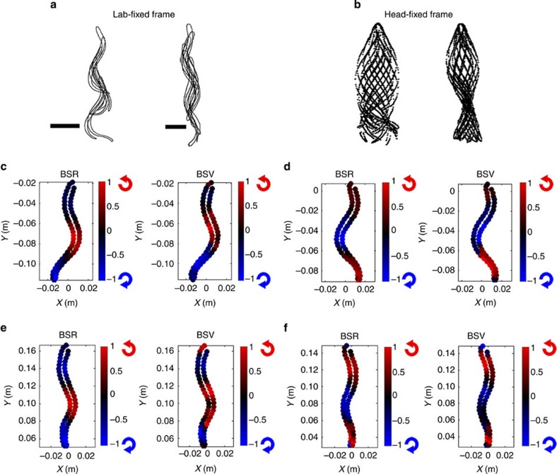
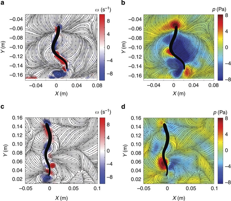
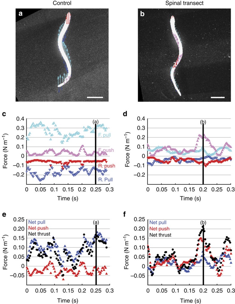
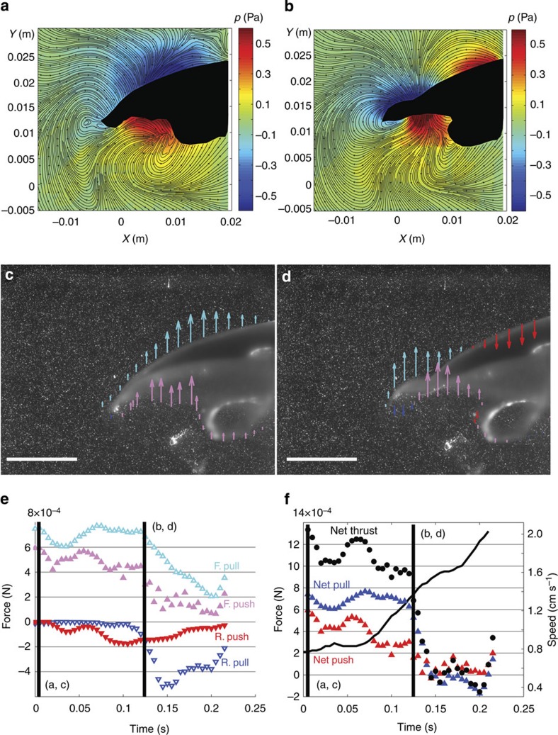
A central and long-standing tenet in the conceptualization of animal swimming is the idea that propulsive thrust is generated by pushing the surrounding water rearward. Inherent in this perspective is the assumption that locomotion involves the generation of locally elevated pressures in the fluid to achieve the expected downstream push of the surrounding water mass. Here we show that rather than pushing against the surrounding fluid, efficient swimming animals primarily pull themselves through the water via suction. This distinction is manifested in dominant low-pressure regions generated in the fluid surrounding the animal body, which are observed by using particle image velocimetry and a pressure calculation algorithm applied to freely swimming lampreys and jellyfish. These results suggest a rethinking of the evolutionary adaptations observed in swimming animals as well as the mechanistic basis for bio-inspired and biomimetic engineered vehicles.


Figures

Figure 1
Figure 1. Body surface rotation and vorticity.
(a) Overlayed outlines of representative control (left) and spinal transect (right) lampreys during a swimming cycle viewed from a lab-fixed frame. Horizontal lines indicate 2 cm scale. (b) Same overlayed outlines as in panel (a) but in a head-fixed frame. (c,d) Comparison of normalized body surface rotation (BSR) and body surface vorticity (BSV) for two phases of a control lamprey swimming cycle. Colour scale indicates local surface angular velocity (for BSR) or fluid vorticity (for BSV) divided by the maximum values on the body. Red and blue icons next to each color bar indicate direction of rotation corresponding to each colour. (e,f) Same data as in panels (c,d) but for a spinal transect lamprey.
Figure 2
Figure 2. Comparison of flow, vorticity and pressure fields for control and spinal transect lampreys.
(a,b) Vorticity and pressure contours, respectively, for a control lamprey at an instant in the swimming cycle. Flow streamlines are overlayed on each. (c,d) Vorticity and pressure contours, respectively, for a spinal transect lamprey at similar phase of swimming cycle as control lamprey. Note that low-pressure regions surround almost the entire body of the control lamprey (b) but are only weakly formed in the transected lamprey (d).
Figure 3
Figure 3. Comparison of pressure contributions to locomotion for control and spinal transect lampreys.
(a,b) Spatial distributions of forward pull (cyan arrows), rearward pull (blue), forward push (magenta) and rearward push (red) due to local fluid pressure for control and spinal transect lampreys, respectively. Arrow length is proportional to local pressure magnitude; arrow direction indicates direction of fluid pressure on animal body. Horizontal line indicates 2 cm scale. (c,d) Temporal trends of pressure contributions over 1–2 swimming cycles for control and spinal transect lampreys, respectively. Vertical lines indicate instants corresponding to data in panels (a,b). (e,f) Temporal trends of net pull, net push and net thrust due to pressure on control and spinal transect lampreys, respectively. Vertical lines indicate instants corresponding to data in panels (a,b). Data represents instantaneous measurements during the swimming of individual animals.
Figure 4
Figure 4. Analysis of pressure dynamics during oblate jellyfish rowing locomotion.
(a,b) Pressure contours and flow streamlines at two instants during a propulsive swimming stroke. Left half of body is indicated by black shape. (c,d) Spatial distributions of forward pull (cyan arrows), rearward pull (blue), forward push (magenta) and rearward push (red) due to local fluid pressure. Arrow length is proportional to local pressure magnitude; arrow direction indicates direction of fluid pressure on animal body. Horizontal lines indicate 1 cm scale. (e) Temporal trends of pressure contributions during a jellyfish propulsive stroke. Vertical lines indicate instants corresponding to data panels as labelled. (f) Temporal trends of net pull, net push and net thrust due to pressure on a jellyfish body. Vertical lines indicate instants corresponding to data panels as labelled. Speed of bell apex is indicated by black curve (scale at right). Data represents instantaneous measurements during the swimming of individual animals.

References

    1. Breder C. M. The locomotion of fishes. Zoologica 4, 159–297 (1926).
    1. Sfakiotakis M., Lane D. & Davies B. Review of fish swimming modes for aquatic locomotion. J. Oceanic Eng. 24, 237–252 (1999).
    1. Vogel S. Comparative Biomechanics: Life's Physical World Princeton University Press (2013).
    1. Lighthill M. J. Large-amplitude elongated-body theory of fish locomotion. Proc. R. Soc. B 179, 125–138 (1971).
    1. Biewener A. A. Animal Locomotion Oxford University Press (2003).

Publication types

LinkOut - more resources