

Mixing in microfluidic devices and enhancement methods
- PMID: 26549938
- PMCID: PMC4634658
- DOI: 10.1088/0960-1317/25/9/094001
Mixing in microfluidic devices and enhancement methods
Abstract
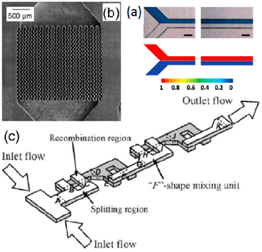
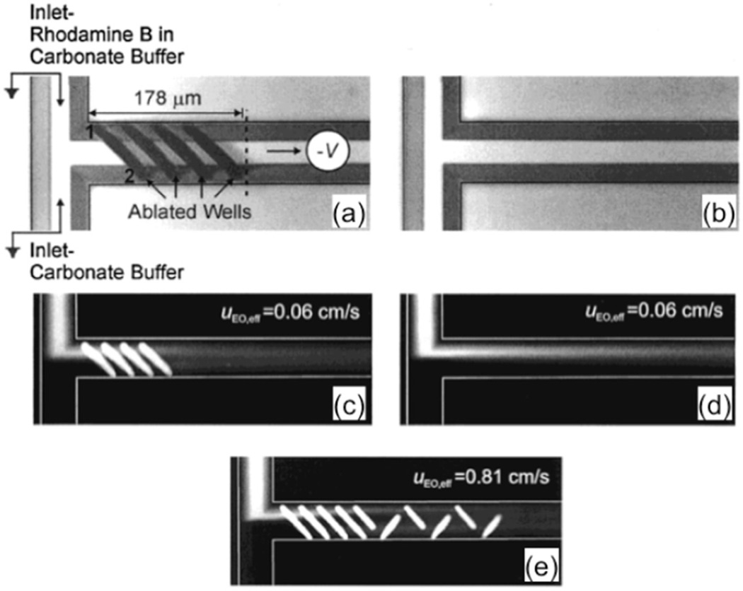
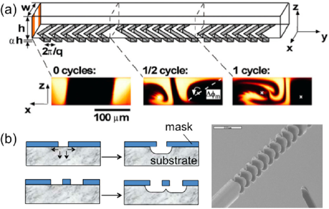
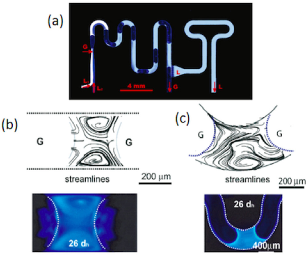
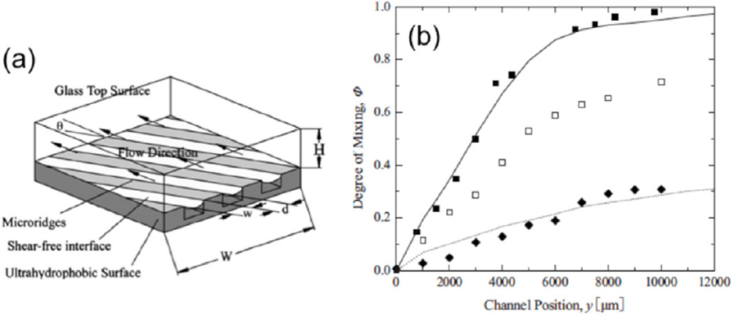
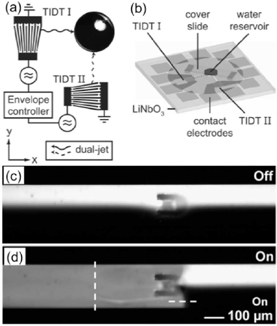
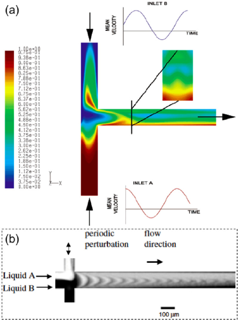
Mixing in microfluidic devices presents a challenge due to laminar flows in microchannels, which result from low Reynolds numbers determined by the channel's hydraulic diameter, flow velocity, and solution's kinetic viscosity. To address this challenge, novel methods of mixing enhancement within microfluidic devices have been explored for a variety of applications. Passive mixing methods have been created, including those using ridges or slanted wells within the microchannels, as well as their variations with improved performance by varying geometry and patterns, by changing the properties of channel surfaces, and by optimization via simulations. In addition, active mixing methods including microstirrers, acoustic mixers, and flow pulsation have been investigated and integrated into microfluidic devices to enhance mixing in a more controllable manner. In general, passive mixers are easy to integrate, but difficult to control externally by users after fabrication. Active mixers usually take efforts to integrate within a device and they require external components (e.g. power sources) to operate. However, they can be controlled by users to a certain degree for tuned mixing. In this article, we provide a general overview of a number of passive and active mixers, discuss their advantages and disadvantages, and make suggestions on choosing a mixing method for a specific need as well as advocate possible integration of key elements of passive and active mixers to harness the advantages of both types.
Keywords: flow controls; microfluidics; micromixers; mixing; review.
Figures
Similar articles
-
Micromixing within microfluidic devices.Top Curr Chem. 2011;304:27-68. doi: 10.1007/128_2011_150. Top Curr Chem. 2011. PMID: 21526435 Review.
-
3D Printed Microfluidic Mixers-A Comparative Study on Mixing Unit Performances.Small. 2019 Jan;15(2):e1804326. doi: 10.1002/smll.201804326. Epub 2018 Dec 10. Small. 2019. PMID: 30548194
-
Mixing Optimization in Grooved Serpentine Microchannels.Micromachines (Basel). 2020 Jan 4;11(1):61. doi: 10.3390/mi11010061. Micromachines (Basel). 2020. PMID: 31947897 Free PMC article.
-
Photoresponsive Passive Micromixers Based on Spiropyran Size-Tunable Hydrogels.Macromol Rapid Commun. 2018 Jan;39(1). doi: 10.1002/marc.201700086. Epub 2017 Apr 18. Macromol Rapid Commun. 2018. PMID: 28418112
-
Passive Mixing inside Microdroplets.Micromachines (Basel). 2018 Apr 1;9(4):160. doi: 10.3390/mi9040160. Micromachines (Basel). 2018. PMID: 30424094 Free PMC article. Review.
Cited by
-
Review of Microfluidic Methods for Cellular Lysis.Micromachines (Basel). 2021 Apr 28;12(5):498. doi: 10.3390/mi12050498. Micromachines (Basel). 2021. PMID: 33925101 Free PMC article. Review.
-
Enabling Technology for Supramolecular Chemistry.Front Chem. 2021 Nov 15;9:774987. doi: 10.3389/fchem.2021.774987. eCollection 2021. Front Chem. 2021. PMID: 34869224 Free PMC article. Review.
-
Rapid AC Electrokinetic Micromixer with Electrically Conductive Sidewalls.Micromachines (Basel). 2021 Dec 27;13(1):34. doi: 10.3390/mi13010034. Micromachines (Basel). 2021. PMID: 35056199 Free PMC article.
-
Towards single cell encapsulation for precision biology and medicine.Adv Drug Deliv Rev. 2023 Oct;201:115010. doi: 10.1016/j.addr.2023.115010. Epub 2023 Jul 16. Adv Drug Deliv Rev. 2023. PMID: 37454931 Free PMC article. Review.
-
Coalescence and mixing dynamics of droplets in acoustic levitation by selective colour imaging and measurement.Sci Rep. 2023 Nov 10;13(1):19590. doi: 10.1038/s41598-023-46008-z. Sci Rep. 2023. PMID: 37949912 Free PMC article.
References
-
- Lo R. Application of microfluidics in chemical engineering. Chem. Eng. Process. Tech. 2013;1:1002.
-
- Hessel V, Löwe H, Schönfield F. Micromixers—a review on passive and active mixing principles. Chem. Eng. Sci. 2005;60:2479.
-
- Aubin J, Ferrando M, Jiricny V. Current methods for characterising mixing and flow in microchannels. Chem. Eng. Sci. 2010;65:2065.
-
- Kockmann N. Convective micromixers—design and industrial applications. J. Mech. Eng. Sci. 2008;222:807.
Grants and funding
LinkOut - more resources
Full Text Sources
Other Literature Sources