Review
. 2015 Nov-Dec;35(7):1965-88.
doi: 10.1148/rg.2015140320.

Medical 3D Printing for the Radiologist

Affiliations
Review

Medical 3D Printing for the Radiologist

Dimitris Mitsouras et al. Radiographics. 2015 Nov-Dec.

Abstract

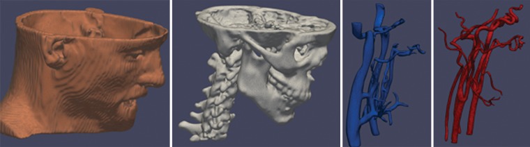
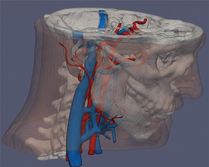
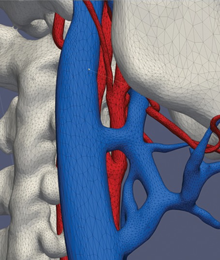
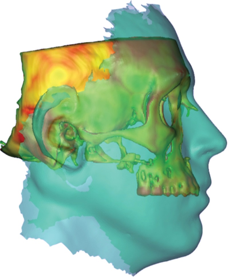
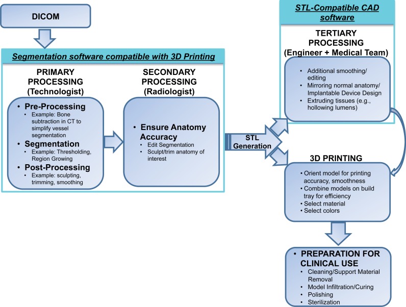
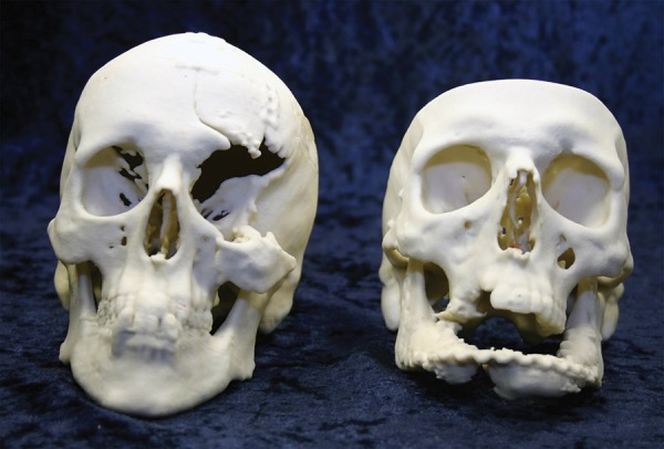
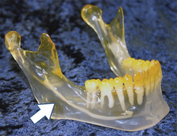
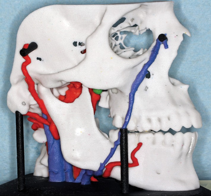
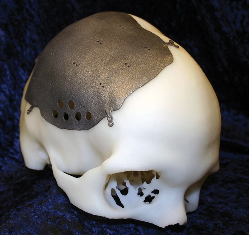
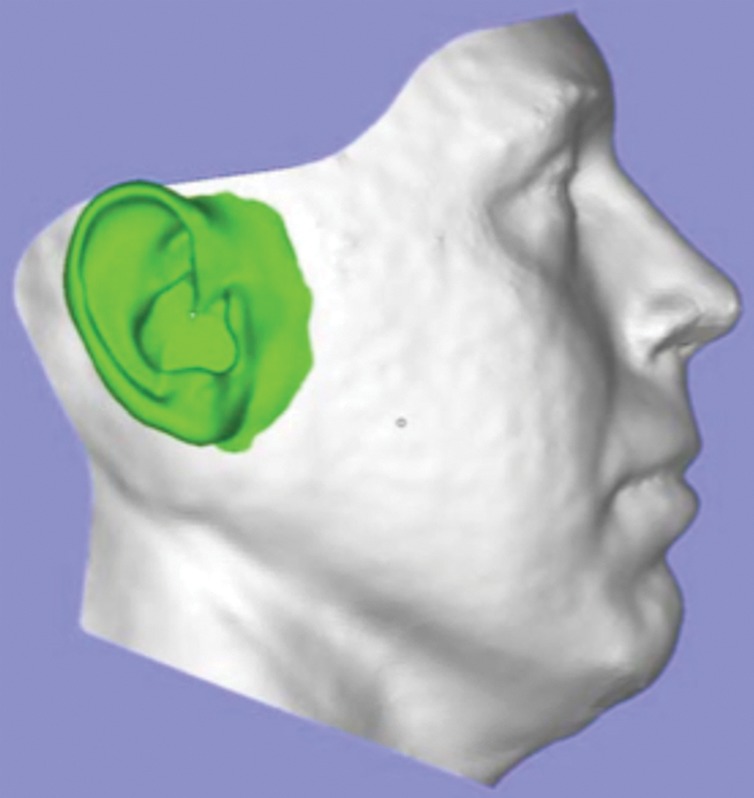
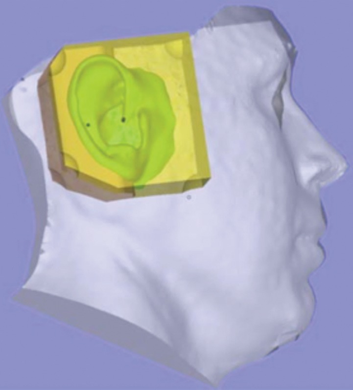
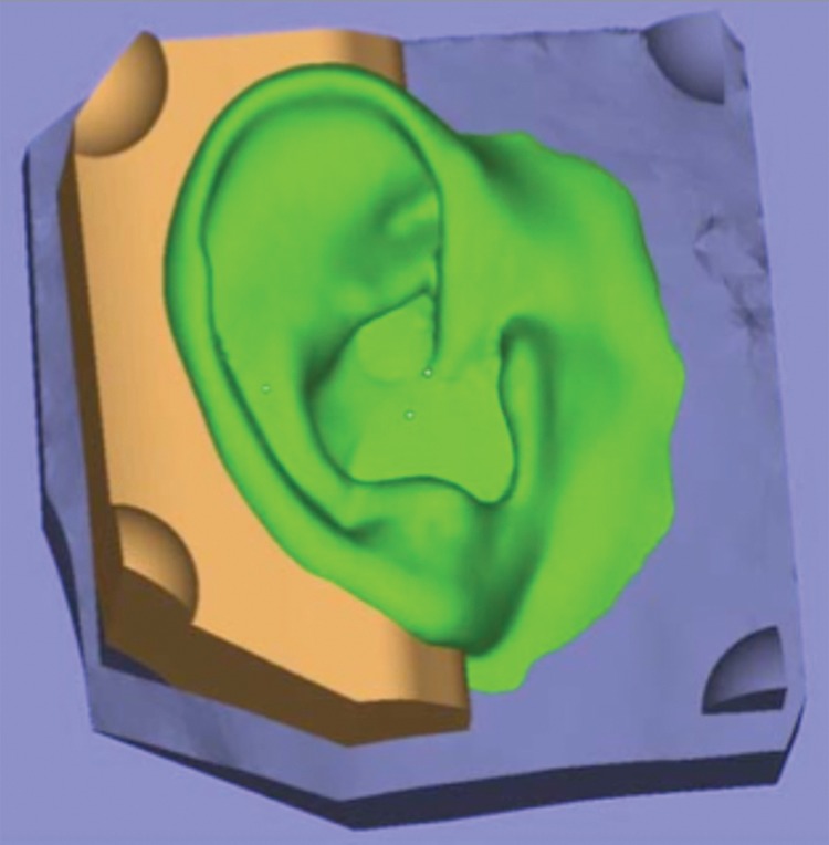
While use of advanced visualization in radiology is instrumental in diagnosis and communication with referring clinicians, there is an unmet need to render Digital Imaging and Communications in Medicine (DICOM) images as three-dimensional (3D) printed models capable of providing both tactile feedback and tangible depth information about anatomic and pathologic states. Three-dimensional printed models, already entrenched in the nonmedical sciences, are rapidly being embraced in medicine as well as in the lay community. Incorporating 3D printing from images generated and interpreted by radiologists presents particular challenges, including training, materials and equipment, and guidelines. The overall costs of a 3D printing laboratory must be balanced by the clinical benefits. It is expected that the number of 3D-printed models generated from DICOM images for planning interventions and fabricating implants will grow exponentially. Radiologists should at a minimum be familiar with 3D printing as it relates to their field, including types of 3D printing technologies and materials used to create 3D-printed anatomic models, published applications of models to date, and clinical benefits in radiology. Online supplemental material is available for this article.


Figures

Figure 1a.
Figure 1a.
Process of 3D printing. (a) Individual tissues depicted on DICOM images are segmented (skin and bone from nonenhanced CT images [left two images]; venous and arterial lumina from contrast-enhanced CT images [right two images]). (b, c) The structures are converted to nonoverlapping (b) and triangulated (STL-format) (c) surfaces that enclose the space occupied by each segmented tissue. A 3D printer can then fabricate these “parts,” defined in STL individual files, potentially with different colors or hard or elastic material.
Figure 1b.
Figure 1b.
Process of 3D printing. (a) Individual tissues depicted on DICOM images are segmented (skin and bone from nonenhanced CT images [left two images]; venous and arterial lumina from contrast-enhanced CT images [right two images]). (b, c) The structures are converted to nonoverlapping (b) and triangulated (STL-format) (c) surfaces that enclose the space occupied by each segmented tissue. A 3D printer can then fabricate these “parts,” defined in STL individual files, potentially with different colors or hard or elastic material.
Figure 1c.
Figure 1c.
Process of 3D printing. (a) Individual tissues depicted on DICOM images are segmented (skin and bone from nonenhanced CT images [left two images]; venous and arterial lumina from contrast-enhanced CT images [right two images]). (b, c) The structures are converted to nonoverlapping (b) and triangulated (STL-format) (c) surfaces that enclose the space occupied by each segmented tissue. A 3D printer can then fabricate these “parts,” defined in STL individual files, potentially with different colors or hard or elastic material.
Figure 2.
Figure 2.
Files for 3D printing (here bone from a CT image) can be combined with a soft-tissue representation (turquoise overlay) acquired from digital photographic methods. Multimodality image registration further enhances the planning of an intervention such as face transplantation by better estimating the relationship between soft tissues and bone. For advanced reconstructive surgeries, these methods are critical for improved functional and cosmetic outcomes.
Figure 3a.
Figure 3a.
Postprocessing of contrast-enhanced CT images of the abdominal aorta. (a) On coronal (middle) and axial (right) CT images, the aorta is segmented by using thresholding (turquoise in a and b), and an enclosing STL surface (3D rendition on left and red outlines in a and b) is generated. (b) On the coronal (middle) and axial (right) CT images, subsequent refinement of the STL file by using standard smoothing and wrapping operations may no longer correctly describe the anatomy.
Figure 3b.
Figure 3b.
Postprocessing of contrast-enhanced CT images of the abdominal aorta. (a) On coronal (middle) and axial (right) CT images, the aorta is segmented by using thresholding (turquoise in a and b), and an enclosing STL surface (3D rendition on left and red outlines in a and b) is generated. (b) On the coronal (middle) and axial (right) CT images, subsequent refinement of the STL file by using standard smoothing and wrapping operations may no longer correctly describe the anatomy.
Figure 4a.
Figure 4a.
Comparison of software environment for 3D printing with visualization tools currently used by radiologists. Screenshots show that generation of an STL file of a skull from CT images uses primarily Hounsfield unit thresholding (a), while more complex structures such as vascular anatomy (b) require use of additional segmentation methods and sculpting.
Figure 4b.
Figure 4b.
Comparison of software environment for 3D printing with visualization tools currently used by radiologists. Screenshots show that generation of an STL file of a skull from CT images uses primarily Hounsfield unit thresholding (a), while more complex structures such as vascular anatomy (b) require use of additional segmentation methods and sculpting.
Figure 5.
Figure 5.
Flowchart shows sample workflow for a radiology-centered 3D printing process. DICOM images are initially processed with compatible segmentation software, and the segmented anatomy is reviewed by the radiologist. An STL file of the selected tissues is then generated. The anatomic parts defined in the STL file can be 3D printed or further manipulated with compatible CAD software to, for example, design prostheses or produce a support platform to hold the parts in place. Final preparation of the tangible 3D-printed model (eg, cleaning and sterilization) is required before clinical use.
Figure 6.
Figure 6.
Three-dimensional printed models used for surgical planning in two patients with facial trauma. After the patients were stabilized, steps for surgical planning included creation of a 3D model for optimal visualization of the extent of bone injury.
Figures 7.
Figures 7.
Stereolithographic model of the lower mandible highlights the teeth and the lingual nerve (arrow).
Figures 8.
Figures 8.
Craniofacial model depicts arteries and veins and is an essential component of planning complex interventions.
Figure 9.
Figure 9.
Three-dimensional printed model created for a patient scheduled for placement of a titanium cranial plate. A model of the patient’s skull was printed with stereolithography. The plate (Ti6AlV4 alloy) was 3D printed with electron-beam technology. This type of surgical planning enables a precise, patient-specific intervention that decreases the time required for the intervention and the risk for peri- and postoperative complications.
Figure 10a.
Figure 10a.
Design and manufacturing of an auricular prosthesis. (a) A representation of the face with a prosthesis is created from digital synthesis of photographs (for the face) and the ear (from DICOM images of the contralateral ear). (b, c) The two pieces of the digital models (b) are used for generation of the definitive silicone prosthesis (c).
Figure 10b.
Figure 10b.
Design and manufacturing of an auricular prosthesis. (a) A representation of the face with a prosthesis is created from digital synthesis of photographs (for the face) and the ear (from DICOM images of the contralateral ear). (b, c) The two pieces of the digital models (b) are used for generation of the definitive silicone prosthesis (c).
Figure 10c.
Figure 10c.
Design and manufacturing of an auricular prosthesis. (a) A representation of the face with a prosthesis is created from digital synthesis of photographs (for the face) and the ear (from DICOM images of the contralateral ear). (b, c) The two pieces of the digital models (b) are used for generation of the definitive silicone prosthesis (c).
Figure 11.
Figure 11.
Three-dimensional printed mask used for full-face transplantation. Models are critical for the recipient as well as the donor. In the donor, a 3D mask is used for the benefit of the deceased’s family and loved ones to replace the superficial features of the tissues that become the allograft used to create the new face for the recipient.
Figure 12.
Figure 12.
Three-dimensional printed vascular models such as that shown provide unprecedented anatomic and volumetric detail and, in addition to assisting in potential treatment planning, can noninvasively provide details needed to determine a surgical or nonsurgical approach for a complex lesion.
Figure 13.
Figure 13.
Binder jetting 3D-printed model focuses on a suprasellar mass (green) and uniquely demonstrates the relationship between the critical arterial anatomy and bone.
Figure 14a.
Figure 14a.
Thoracic 3D-printed model. (a) Three-dimensional printed model of a normal tracheobronchial tree. (b) Fiberoptic view through the bronchus intermedius of the 3D model. (c) Fiberoptic view through the bronchus intermedius in the actual anatomy. Note the similarity between the printed model at simulated bronchoscopy and the actual anatomy. (Fig 14 adapted and reprinted, with permission, from reference .)
Figure 14b.
Figure 14b.
Thoracic 3D-printed model. (a) Three-dimensional printed model of a normal tracheobronchial tree. (b) Fiberoptic view through the bronchus intermedius of the 3D model. (c) Fiberoptic view through the bronchus intermedius in the actual anatomy. Note the similarity between the printed model at simulated bronchoscopy and the actual anatomy. (Fig 14 adapted and reprinted, with permission, from reference .)
Figure 14c.
Figure 14c.
Thoracic 3D-printed model. (a) Three-dimensional printed model of a normal tracheobronchial tree. (b) Fiberoptic view through the bronchus intermedius of the 3D model. (c) Fiberoptic view through the bronchus intermedius in the actual anatomy. Note the similarity between the printed model at simulated bronchoscopy and the actual anatomy. (Fig 14 adapted and reprinted, with permission, from reference .)
Figure 15.
Figure 15.
Flexible binder jetting model of a severely calcified aorta used in planning for a transcatheter aortic valve replacement. Red = normal vessel wall, tan = calcium. (Adapted and reprinted, with permission, from reference .)
Figure 16a.
Figure 16a.
Material jetting model of an aorta, produced by segmentation of images from high-resolution contrast-enhanced MR angiography. (a, b) Full (a) and close-up (b) views of the model show severe kinking and a subclavian artery with a mild aneurysm. (c) Supra-aortic vessel branching (arrows) is seen from inside the model. (Fig 16 adapted and reprinted, with permission, from reference .)
Figure 16b.
Figure 16b.
Material jetting model of an aorta, produced by segmentation of images from high-resolution contrast-enhanced MR angiography. (a, b) Full (a) and close-up (b) views of the model show severe kinking and a subclavian artery with a mild aneurysm. (c) Supra-aortic vessel branching (arrows) is seen from inside the model. (Fig 16 adapted and reprinted, with permission, from reference .)
Figure 16c.
Figure 16c.
Material jetting model of an aorta, produced by segmentation of images from high-resolution contrast-enhanced MR angiography. (a, b) Full (a) and close-up (b) views of the model show severe kinking and a subclavian artery with a mild aneurysm. (c) Supra-aortic vessel branching (arrows) is seen from inside the model. (Fig 16 adapted and reprinted, with permission, from reference .)
Figures 17a.
Figures 17a.
Heterotopic ossification. (a) Surface rendering of an STL model of the pelvis and femurs. (b) Three-dimensional printed model helps define the surgical approach and treatment plan before the procedure, leading to a more rapid procedure with fewer complications.
Figures 17b.
Figures 17b.
Heterotopic ossification. (a) Surface rendering of an STL model of the pelvis and femurs. (b) Three-dimensional printed model helps define the surgical approach and treatment plan before the procedure, leading to a more rapid procedure with fewer complications.
Figures 18.
Figures 18.
Surface rendering of an STL model of a complex pelvic fracture. Note that both femurs were removed to enhance fracture visualization for intervention planning.
Figure 19.
Figure 19.
Three-dimensional printed model of a knee includes the vasculature to assist in planning for intervention.
Figure 20.
Figure 20.
Three-dimensional printed model of a complex fracture. For this patient, commercially available hardware (silver) was prebent and shaped on the basis of the printed model. This saves considerable intraoperative time and cost when compared with standard procedures, where the hardware choices are determined at standard CT, in the operating room, or typically with a combination of both.
Figure 21a.
Figure 21a.
Three-dimensional printed model of the aortic lumen used for training. (a) Silicon model was produced by molding onto a solid model of the aortic lumen that was reproduced with binder jetting. The 3D-printed solid lumen model used as the mold core was broken for removal from the cured silicone layer. (b) Image shows fluoroscopically guided catheterization and stent placement performed on the elastic silicone model. (Fig 21 adapted and reprinted, with permission, from reference .)
Figure 21b.
Figure 21b.
Three-dimensional printed model of the aortic lumen used for training. (a) Silicon model was produced by molding onto a solid model of the aortic lumen that was reproduced with binder jetting. The 3D-printed solid lumen model used as the mold core was broken for removal from the cured silicone layer. (b) Image shows fluoroscopically guided catheterization and stent placement performed on the elastic silicone model. (Fig 21 adapted and reprinted, with permission, from reference .)
Figure 22a.
Figure 22a.
Three-dimensional printed phantom used for CT angiographic experiments. (a) In vivo CT angiograms show segmentation of the left anterior descending coronary artery and first and second diagonal branches. (b) An STL model of the luminal surface (turquoise) was created and was augmented with flow diffusers (red) and an outer shell (transparent gray) fitted with Luer locks. The space between the lumen and outer shell was then printed with a vat photopolymerization machine. (c) The finished 3D-printed phantom can be used for “in vitro” contrast-enhanced CT angiographic experiments.
Figure 22b.
Figure 22b.
Three-dimensional printed phantom used for CT angiographic experiments. (a) In vivo CT angiograms show segmentation of the left anterior descending coronary artery and first and second diagonal branches. (b) An STL model of the luminal surface (turquoise) was created and was augmented with flow diffusers (red) and an outer shell (transparent gray) fitted with Luer locks. The space between the lumen and outer shell was then printed with a vat photopolymerization machine. (c) The finished 3D-printed phantom can be used for “in vitro” contrast-enhanced CT angiographic experiments.
Figure 22c.
Figure 22c.
Three-dimensional printed phantom used for CT angiographic experiments. (a) In vivo CT angiograms show segmentation of the left anterior descending coronary artery and first and second diagonal branches. (b) An STL model of the luminal surface (turquoise) was created and was augmented with flow diffusers (red) and an outer shell (transparent gray) fitted with Luer locks. The space between the lumen and outer shell was then printed with a vat photopolymerization machine. (c) The finished 3D-printed phantom can be used for “in vitro” contrast-enhanced CT angiographic experiments.
Figure 23.
Figure 23.
Newer material jetting 3D printing technologies and materials allow direct printing of a compliant vessel wall (2–3 mm thickness) with sufficient tensile strength to be used for realistic flow physiology experiments. Images show an in vitro contrast-enhanced CT angiographic experiment performed by using a pulsatile flow pump and ultrasonic flowmeter (green inset a) attached to a coronary phantom (red inset b), which was fabricated by segmentation of a patient’s contrast-enhanced CT angiograms. The lower panel shows the phantom and CT angiograms obtained in two cardiac phases (systole, left; diastole, right) (Movie). (Experiment performed in collaboration with Ciprian Ionita, PhD, and Steven Rudin, PhD, State University of New York at Buffalo, Buffalo, NY.)

Comment in

References

    1. Fishman EK, Drebin B, Magid D, et al. . Volumetric rendering techniques: applications for three-dimensional imaging of the hip. Radiology 1987;163(3):737–738. - PubMed
    1. Rubin GD, Dake MD, Napel SA, McDonnell CH, Jeffrey RB, Jr. Three-dimensional spiral CT angiography of the abdomen: initial clinical experience. Radiology 1993;186(1): 147–152. - PubMed
    1. Wohlers Associates, Inc . Wohlers report 2013: additive manufacturing and 3D printing state of the industry. Fort Collins, Colo: Wohlers Associates, Inc, 2013.
    1. Mitsouras D, Dill KE, Kumamaru KK, Steigner ML, Rybicki FJ, III. 3-D printing: bridging the gap between theory and practice [abstr]. In: Radiological Society of North America Scientific Assembly and Annual Meeting Program. Oak Brook, Ill: Radiological Society of North America, 2013; 109.
    1. Hiller J, Lipson H. STL 2.0: a proposal for a universal multi-material Additive Manufacturing File format. Proceedings of the Solid Freeform Fabrication Symposium 2009. Austin, Texas, 2009; 266–278.

Publication types

Substances