. 2011 Nov 1;59(6):591-612.
doi: 10.3397/1.3659660.

Development of elastomeric isolators to reduce roof bolting machine drilling noise

Affiliations

Development of elastomeric isolators to reduce roof bolting machine drilling noise

Robert Michael et al. Noise Control Eng J. .

Abstract

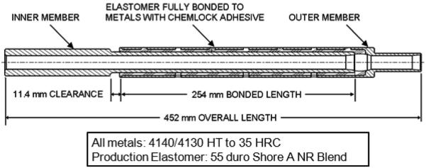
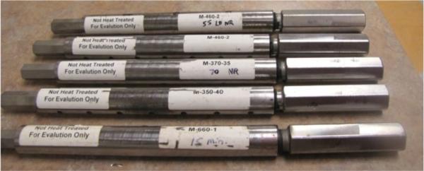
Among underground coal miners, hearing loss remains one of the most common occupational illnesses. In response to this problem, the National Institute for Occupational Safety and Health (NIOSH) Office of Mine Safety and Health Research (OMSHR) conducts research to reduce the noise emission of underground coal-mining equipment, an example of which is a roof bolting machine. Field studies show that, on average, drilling noise is the most significant contributor to a roof bolting machine operator's noise exposure. NIOSH OMSHR has determined that the drill steel and chuck are the dominant sources of drilling noise. NIOSH OMSHR, Corry Rubber Corporation, and Kennametal, Inc. have developed a bit isolator that breaks the steel-to-steel link between the drill bit and drill steel and a chuck isolator that breaks the mechanical connection between the drill steel and the chuck, thus reducing the noise radiated by the drill steel and chuck, and the noise exposure of the roof bolter operator. This paper documents the evolution of the bit isolator and chuck isolator including various alternative designs which may enhance performance. Laboratory testing confirms that production bit and chuck isolators reduce the A-weighted sound level generated during drilling by 3.7 to 6.6 dB. Finally, this paper summarizes results of a finite element analysis used to explore the key parameters of the drill bit isolator and chuck isolator to understand the impact these parameters have on noise.


Figures

Fig. 1
Fig. 1
Drill steel accelerometers and slipring assembly.
Fig. 2
Fig. 2
Typical drill steel acceleration, hexagonal drill steel, 35-mm-diameter bit, granite drill media.
Fig. 3
Fig. 3
Beamforming image for baseline drilling, 100 dBA at the operators’ position.
Fig. 4
Fig. 4
Jaw-type coupling with 58 Shore D urethane spider.
Fig. 5
Fig. 5
Beamforming image for drilling with the jaw-type coupling, 96 dBA at the operators’ position.
Fig. 6
Fig. 6
First generation production designs of isolators for use with 35-mm-diameter drill bits.
Fig. 7
Fig. 7
Cross-section of first generation production design chuck isolator.
Fig. 8
Fig. 8
Design requirements for load and corresponding stiffness directions.
Fig. 9
Fig. 9
Isolators bonded with elastomers from Table 5.
Fig. 10
Fig. 10
MTS810 test system used to measure axial load capacity and static and dynamic stiffness.
Fig. 11
Fig. 11
Apparatus used for testing torsional load capacity and static torsion stiffness.
Fig. 12
Fig. 12
Axial test, static load-deflection curves.
Fig. 13
Fig. 13
Dynamic axial stiffness, K′, vs. frequency.
Fig. 14
Fig. 14
Torsion test, static torque vs. angle of twist.
Fig. 15
Fig. 15
Locus of possible axial and torsion stiffness for production isolator bonded with various durometer elastomers.
Fig. 16
Fig. 16
Test setup for sound level measurements at the operator’s ear.
Fig. 17
Fig. 17
A-wtd SPL in 1/3-octave bands for hydraulics and baseline drilling conditions.
Fig. 18
Fig. 18
A-wtd SPL in 1/3-octave bands for baseline and with bit isolators.
Fig. 19
Fig. 19
A-wtd SPL in 1/3-octave bands for baseline and with only a chuck isolator.
Fig. 20
Fig. 20
A-wtd SPL in 1/3-octave bands: baseline; 58 duro NR BISO; and 58 duro NR BISO with 58 duro NR CISO.
Fig. 21
Fig. 21
A-wtd SPL in 1/3-octave bands for baseline; 45 duro NR BISO and CISO; 58 duro NR BISO and CISO; and 68 duro NR BISO and CISO.
Fig. 22
Fig. 22
A-wtd SPL in 1/3-octave bands for baseline and best three tests: 45 duro NR BISO, 58 duro NR BISO, and 58 duro NR BISO with 58 duro NR CISO.
Fig. 23
Fig. 23
Second generation isolator (QC-20377) with male connections at both ends which can be installed into standard 35 mm drill rod.
Fig. 24
Fig. 24
Cross section of second generation isolator (QC-20377).
Fig. 25
Fig. 25
Other design options to increase load capacity and improve isolator life.
Fig. 26
Fig. 26
Alternative chuck isolator with standard QC-20377 drill bit isolator.
Fig. 27
Fig. 27
EST Chuck Isolator. This alternative chuck isolator design can be used for development. By adding/ subtracting isolators, stiffness can be adjusted to find optimal properties which then can be designed into a production version (alternatively this design can be used for short term production – no tooling required).
Fig. 28
Fig. 28
EST Chuck Isolator with possible configurations.
Fig. 29
Fig. 29
Pancake Chuck Isolator. This alternative chuck isolator design uses flat elastomeric disks. The size, durometer, arrangement (series or parallel) and pre-compression can all be modified to produce broad range of stiffness values.
Fig. 30
Fig. 30
Molded disks used in pancake chuck isolator. The size, durometer and arrangement of these disks (i.e. parallel or series arrangement) and amount of pre-compression can greatly alter the stiffness of the coupling.
Fig. 31
Fig. 31
Possible production designs for chuck isolator. All these designs incorporate bonded elastomer for consistent stiffness. The appropriate configuration will be determined after testing is completed on the prototype chuck isolators.
Fig. 32
Fig. 32
Model used in finite element analysis. 1.2 meter-long drill rod model with separate body to represent drill bit body. Fixed boundary conditions at chuck and at drilling media. Load can be FY (tangential) or FZ (axial), and is placed off-center on the drill bit tip, representing the drill bit cutting edge interaction with the drilling media (rock).
Fig. 33
Fig. 33
Estimated sound power level spectra for the 500 through 3150-Hz 1/3 octave bands for Cases 0, 1, 2, 6 and 7.

References

    1. 1996. National Institute for Occupational Safety and Health, National Occupational Agenda, Department of Health and Human Services Publication No. 96-115.
    1. Title 30 CFR Part 62, 2000–2005, U.S. Department of Labor, Mine Safety and Health Administration, Information Resource Center.
    1. Peterson Jeffrey Shawn, Alcorn Lynn. Results of noise measurements from underground testing of a roof bolting machine duty cycle. NoiseCon07. 2007
    1. Hawkes I, Burks JA. Investigation of Noise and Vibration in Percussive Drill Rods. Int. J. Rock, Mech, Min. Sci. & Geomech. 1979;16:363–376.
    1. Carlvik I. The Generation of Bending Vibrations in Drill Rods. Int. J. Rock, Mech, Min. Sci. & Geomech. 1981;18:167–172.

LinkOut - more resources