. 2015 Nov 17:6:8818.
doi: 10.1038/ncomms9818.

The antisymmetry of distortions

Affiliations

The antisymmetry of distortions

Brian K VanLeeuwen et al. Nat Commun. .

Abstract

Distortions are ubiquitous in nature. Under perturbations such as stresses, fields or other changes, a physical system reconfigures by following a path from one state to another; this path, often a collection of atomic trajectories, describes a distortion. Here we introduce an antisymmetry operation called distortion reversal that reverses a distortion pathway. The symmetry of a distortion pathway is then uniquely defined by a distortion group; it has the same form as a magnetic group that involves time reversal. Given its isomorphism to magnetic groups, distortion groups could have a commensurate impact in the study of distortions, as the magnetic groups have had in the study of magnetic structures. Distortion symmetry has important implications for a range of phenomena such as structural and electronic phase transitions, diffusion, molecular conformational changes, vibrations, reaction pathways and interface dynamics.


Figures
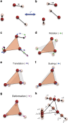
Figure 1
Figure 1. A simple example of a distortion and its decomposition.
Three atoms (red spheres) are displaced by vectors u (black arrows) to their new positions (pink spheres) in a. The collection of the three displacement vectors, u, constitute a distortion. The distortion-reversal operation, 1*, reverses these displacements, u, and hence the distortion, as shown in b. The blue double-headed arrow indicates that repeated application of 1* can reverse between a and b. In c, each displacement vector, u, is decomposed into pure rotation (green arrows) (d), pure translation (purple arrows) (e), pure scaling (blue arrows) (f), and the remainder deformation (pink arrows) (g). As a guide to the eye, the orange and grey triangles in cg indicate the initial and final configurations of the atoms, respectively. Linear atomic trajectories depicted here can be parameterized by −1≤λ≤1, as shown in h. Distortion-reversal operation, 1*, can thus be alternately viewed as a reversal of λ for a fixed u. This definition of 1* reversing the sign of λ, and not the reversal of displacement vectors, will be used in the rest of this article.
Figure 2
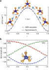
Figure 2. Distortion symmetry of the PF5 pseudorotation.
The PF5 molecule undergoes pseudorotation from the λ=−1 state (left inset in a, blue atom is P and yellow atoms are F), through a transition state at λ=0 (middle inset in a), to the λ=+1 state (right inset in a). Pairs of static images at λ and −λ are related by a fourfold rotation along the PF1 bond (see inset in b for atom labels). The orange (light blue) arrows represent portions of the pathway going in the direction of increasing (decreasing) λ. The path segment over an infinitesimal path segment, Δλ to the left of λ=0 is transformed under 4 into the path segment −Δλ to the right of λ=0. The displacements of atoms between consecutive images on the left can be related to the displacements of atoms between consecutive images on the right. Thus 4 transforms images between λ and −λ and also the atomic displacements between consecutive images in such a way that the overall distortion path remains invariant. The set of all such operations that leave this pathway invariant form the complete distortion-symmetry group of this pathway, 4mm, where starred symmetries are distortion reversing and are highlighted by blue colour. The blue circles in a are energies from NEB calculations and the black line is the symmetrized fit as guaranteed by the 4mm symmetry group. The PF1 bond length (labelled in the inset in b, which shows the superimposed images of the molecule along the distortion path) as a function of λ for the NEB calculated path is plotted in b as blue circles; it is also guaranteed to be an even function with respect to λ, as is consistent with the symmetrized fit (blue line). Similarly, the PF2 (green circles and line) and PF3 (red circles and line) bond lengths are required by the 4mm symmetry to be mirror images of each other; this is consistent with the plot in b.
Figure 3
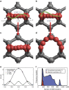
Figure 3. The consequences of distortion symmetry and balanced forces for NEB calculations.
(ad) Superimposed images along oxygen (red atom) diffusion paths on graphene (grey carbon atoms connected by grey bonds). In a and b, an initial linear path is assumed for the diffusion of a single oxygen atom from right (λ=−1) to left (λ=+1), across a C6 graphene ring. The symmetry of the path in a and b is mm2; the symmetry traps the path and prevents convergence to a minimum-energy pathway (MEP). To break the mm2 symmetry, we perturb this linear path as mm2→2 and mm2→1, respectively, as shown schematically exaggerated as green curves in a and b and indicated by the text in the inset. (c,d) The final paths after NEB relaxation starting from the perturbed paths of a and b, respectively, as indicated by red vertical arrows. The paths c and d have distortion symmetries of 2 and m, respectively. The 2 symmetry continues to trap the transition state (just like mm2 did for the linear path), whereas the initial path with trivial symmetry can correctly converge to a MEP with m symmetry. (e) The calculated energies of the images and the interpolation provided by QE's NEB module. (f) Results for an example two-dimensional potential energy surface inspired by the above problem, using a simple NEB implementation. The plots are smoothed and rescaled histograms showing the frequency of NEB convergence at a given number of iterations in this example system for 100,000 randomly generated initial paths each with m or with trivial symmetry of 1. The two curves are rescaled to the same maximum height. Symmetrizing using the correct symmetry, m (red curve) reduced the number of NEB iterations needed in 98.97% of test cases. The average reduction was ∼2.3 × as compared with conventional symmetry (blue curve). This demonstrates that distortion symmetry can reduce the number of NEB iterations necessary for convergence.
Figure 4
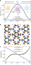
Figure 4. The application of distortion symmetry to a distortion of β-BaB2O4.
The mostly rigid rotation of the B3O6 rings leads to two variants of β-BaB2O4 with R3c symmetry group, the λ=−1 variant (inset in orange in a and the λ=+1 variant (inset in cyan in a), transforming through a transition state at λ=0 (inset in magenta in a) with a symmetry of formula image. The symmetry of this path, formula image, requires that the energy profile in a is symmetric. (b) The superimposed images of β-BaB2O4 along the distortion pathway; their colour varies from orange, through magenta to cyan as λ varies from −1 through 0 to +1. (c) The optical second harmonic generation tensor coefficients along this pathway calculated by Cammarata and Rondinelli (red, green and blue circles) and a polynomial fit (red, green and blue lines) using only the coefficients that are consistent with formula image point-group symmetry. Distortion symmetry predicts that these coefficients will be odd functions of the distortion parameter, λ, and zero when λ=0.

Figure 5
Figure 5. Four different example distortions in crystals and their distortion symmetry groups.
Each panel depicts the superimposed structures through a distortion from λ=−1 to λ=+1 so that the movement of the atoms appears in the form of a blur. (a) A distortion pathway between two domain variants of a right-handed alpha quartz, passing through beta quartz at λ=0, with a distortion group of P6422. (b) A distortion of ferroelectric PbTiO3 created by a linear interpolation between opposite (180°) polarization states; the pathway has a symmetry of P4/mmm. (c) A distortion of YMnO3 between opposite ferroelectric domain variants with a distortion symmetry of P63/mcm. (d) A B1u normal mode of YBa2Cu3O6.5 with a distortion symmetry of Pmmm.

References

    1. Pechukas P. Transition state theory. Annu. Rev. Phys. Chem. 32, 159–177 (1981) .
    1. Bone R. G. A. Deducing the symmetry operations generated at a transition state. Chem. Phys. Lett. 193, 557–564 (1992) .
    1. McIver J. W. & Stanton R. E. Symmetry selection rules for transition states. J. Am. Chem. Soc. 94, 8618–8620 (1972) .
    1. Henkelman G. & Jónsson H. Improved tangent estimate in the nudged elastic band method for finding minimum energy paths and saddle points. J. Chem. Phys. 113, 9978 (2000) .
    1. Campbell B. J., Stokes H. T., Tanner D. E. & Hatch D. M. ISODISPLACE: a web-based tool for exploring structural distortions. J. Appl. Crystallogr. 39, 607–614 (2006) .

Publication types

LinkOut - more resources