

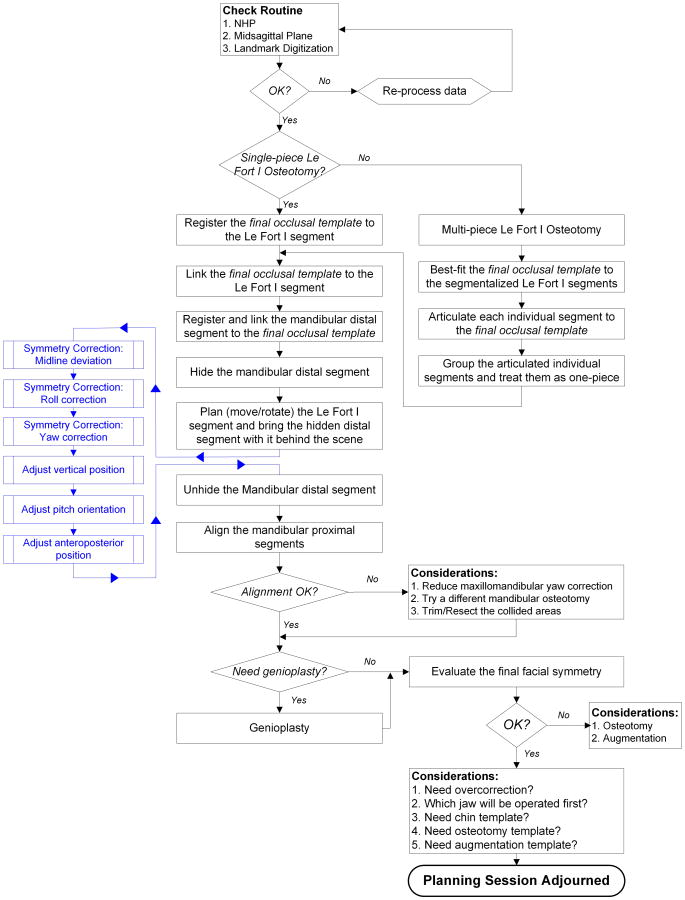
Algorithm for planning a double-jaw orthognathic surgery using a computer-aided surgical simulation (CASS) protocol. Part 1: planning sequence
- PMID: 26573562
- PMCID: PMC4653096
- DOI: 10.1016/j.ijom.2015.06.006
Algorithm for planning a double-jaw orthognathic surgery using a computer-aided surgical simulation (CASS) protocol. Part 1: planning sequence
Abstract
The success of craniomaxillofacial (CMF) surgery depends not only on the surgical techniques, but also on an accurate surgical plan. The adoption of computer-aided surgical simulation (CASS) has created a paradigm shift in surgical planning. However, planning an orthognathic operation using CASS differs fundamentally from planning using traditional methods. With this in mind, the Surgical Planning Laboratory of Houston Methodist Research Institute has developed a CASS protocol designed specifically for orthognathic surgery. The purpose of this article is to present an algorithm using virtual tools for planning a double-jaw orthognathic operation. This paper will serve as an operation manual for surgeons wanting to incorporate CASS into their clinical practice.
Keywords: CASS; computer-aided surgical simulation; dentofacial deformity; double-jaw orthognathic surgery; planning algorithm.
Copyright © 2015 International Association of Oral and Maxillofacial Surgeons. Published by Elsevier Ltd. All rights reserved.
Figures


References
-
- Gateno J, Xia J, Teichgraeber JF, Rosen A. A new technique for the creation of a computerized composite skull model. J Oral Maxillofac Surg. 2003;61:222–227. - PubMed
-
- Xia JJ, Gateno J, Teichgraeber JF. Three-dimensional computer-aided surgical simulation for maxillofacial surgery. Atlas Oral Maxillofac Surg Clin North Am. 2005;13:25–39. - PubMed
-
- Swennen GR, Mommaerts MY, Abeloos J, De Clercq C, Lamoral P, Neyt N, Casselman J, Schutyser F. The use of a wax bite wafer and a double computed tomography scan procedure to obtain a three-dimensional augmented virtual skull model. J Craniofac Surg. 2007;18:533–539. - PubMed
-
- Swennen GR, Mollemans W, Schutyser F. Three-dimensional treatment planning of orthognathic surgery in the era of virtual imaging. J Oral Maxillofac Surg. 2009;67:2080–2092. - PubMed
Publication types
MeSH terms
Grants and funding
LinkOut - more resources
Full Text Sources
Other Literature Sources
