Review
. 2015 Nov:90-91:92-122.
doi: 10.1016/j.pnmrs.2015.10.001. Epub 2015 Oct 23.

Spatial reorientation experiments for NMR of solids and partially oriented liquids

Affiliations
Review

Spatial reorientation experiments for NMR of solids and partially oriented liquids

Rachel W Martin et al. Prog Nucl Magn Reson Spectrosc. 2015 Nov.

Abstract

Motional reorientation experiments are extensions of Magic Angle Spinning (MAS) where the rotor axis is changed in order to average out, reintroduce, or scale anisotropic interactions (e.g. dipolar couplings, quadrupolar interactions or chemical shift anisotropies). This review focuses on Variable Angle Spinning (VAS), Switched Angle Spinning (SAS), and Dynamic Angle Spinning (DAS), all of which involve spinning at two or more different angles sequentially, either in successive experiments or during a multidimensional experiment. In all of these experiments, anisotropic terms in the Hamiltonian are scaled by changing the orientation of the spinning sample relative to the static magnetic field. These experiments vary in experimental complexity and instrumentation requirements. In VAS, many one-dimensional spectra are collected as a function of spinning angle. In SAS, dipolar couplings and/or chemical shift anisotropies are reintroduced by switching the sample between two different angles, often 0° or 90° and the magic angle, yielding a two-dimensional isotropic-anisotropic correlation spectrum. Dynamic Angle Spinning (DAS) is a related experiment that is used to simultaneously average out the first- and second-order quadrupolar interactions, which cannot be accomplished by spinning at any unique rotor angle in physical space. Although motional reorientation experiments generally require specialized instrumentation and data analysis schemes, some are accessible with only minor modification of standard MAS probes. In this review, the mechanics of each type of experiment are described, with representative examples. Current and historical probe and coil designs are discussed from the standpoint of how each one accomplishes the particular objectives of the experiment(s) it was designed to perform. Finally, applications to inorganic materials and liquid crystals, which present very different experimental challenges, are discussed. The review concludes with perspectives on how motional reorientation experiments can be applied to current problems in chemistry, molecular biology, and materials science, given the many advances in high-field NMR magnets, fast spinning, and sample preparation realized in recent years.

Keywords: Dynamic angle spinning; Instrumentation; Liquid crystals; Switched angle spinning; Variable angle spinning.


Figures

Figure 1:
Figure 1:
The values of P2(cos β) and P4(cos β) are plotted over a range of 0 to 90°, relative to B0. The angles where the respective functions go to zero are indicated with dashed lines. There exists no one sample spinning angle for which P2(cos β) and P4(cos β) are both averaged out, which has important implications for spatial reorientation experiments.
Figure 2:
Figure 2:
Reduced Wigner matrix elements as a function of rotor angle (A) Second-order elements (B) Fourth-order elements [73]
Figure 3:
Figure 3:
Data collection schemes for multidimensional isotropic/anisotropic correlations (a) Traditional Cartesian sampling scheme: the spin system evolves during the time ta under the effects of the anisotropic interactions. FIDs are then acquired as a function of the independent parameter time ti when the system evolves under the isotropic interaction [80]. (b) VACSY: the system evolves in the (ta, ti) plane and the direction is changed within the two boundary values P2(cos β) = −0.5 and P2(cos β) = 1, by changing the spinning axis angle β. The value of P2(cos β) cannot be made to go below −0.5 or above 1 no matter the spinning angle, limiting the coverage of the space [80]. (c) DACSY: Performing a series of 2D DAS acquisitions under various sets of complementary (β1, β2) spinning angles creates a set of t-space cross sections. This set of cross sections then make up the 3D DACSY spectra used for quadrupolar nuclei [84].
Figure 4:
Figure 4:
(a) The SEDORFS pulse sequence starts away from the magic angle. 1H-13C cross-polarization is followed by a dipolar evolution period with a π-pulse on 13C to refocus isotropic chemical shift. The 15N π-pulses induce dipolar dephasing. At the end of the evolution period, the magnetization is stored along the z-axis during the angle switch, and then read out at the magic angle. The experiment is performed with and without the 15N dephasing pulses, and the dipolar coupling value is obtained from the ratio of the signal obtained ΔS/S, similar to the data acquisition scheme in REDOR. Figure adapted from [86] (b) Representative SEDORFS data for the model compound [L-4 13C-, amide- 15N] asparagine, showing the effect of the spinning angle on the dipolar couplings. Here the experiment was performed with the spinning angle during the evolution period set to 90° (open circles). The SEDOR experiment (filled circles) is equivalent to SEDORFS at 0°, which was not directly performed because it was not possible in the probe used, which had a solenoid coil. The solid lines represent the corresponding theoretical curves. Figure reprinted from [86].
Figure 5:
Figure 5:
Experimental 1H-13C cross-polarization arrays at different spinning angles. The 13C rf field strength was held constant at 28 kHz and the 1H nutation frequency was arrayed from 15–55 kHz. The rotor frequency was 5 kHz at all angles. The 1H 90° pulse length was 5.5 μs, corresponding to a 1H power 45.45 kHz. As expected, at the magic angle the n = +2 and n = ±1 sidebands give the strongest signals. The n = −2 sideband is weak because at this rotor frequency the efficiency of CP declines at rf amplitudes below 20 kHz. Above the magic angle the center band is more pronounced, and begins to dominate at small spinning angles, resembling the static case at 0°. The situation at 90° is quite different - the n = ±1 conditions disappear and the match array is dominated by the n = 0 and n = ±2 bands.
Figure 6:
Figure 6:
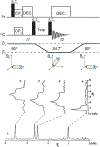
Top: SAS pulse sequence used for correlating the CSA powder pattern to the isotropic spectrum. Adapted from [113]. After a CP preparation period, magnetization evolves under the CSA at a spinning angle of 90°. The magnetization is then stored along the z–axis while the rotor hops to the magic angle for detection. Bottom: SAS NMR data showing the CSA patterns associated with particular sites in a 13C SAS spectrum of polycrystalline p-methoxybenzene. (a) The isotropic spectrum, collected in F2 at the magic angle. (b)-(e) Slices from the F1 dimension for each isotropic carbon frequency. These powder patterns are half as wide relative to the static spectrum of this molecule because the rotor is spinning at 90°, where the value of P2(cos β) is 12. Reprinted from [113].
Figure 7:
Figure 7:
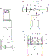
Magic-Angle Flipping probe: probe assembly (a) and the probe head in an exploded view to show all of the parts (b) and assembled (c) [bearing and drive air shafts highlighted in red]. Parts: 1) 4mm stator housing, 2) probe head pulley, 3) 4mm coil mount, 4) top ring, 5) pulley-stop, 6) stator housing post, 7) pulley-side stator housing post, 8) Head mount, 9 & 10) stator housing post, 11) male slip ring, 12 & 13) female slip rings, 14) thin film attachments. Drawings courtesy of Philip Grandinetti.
Figure 8:
Figure 8:
Measured B1 field strengths for a solenoid and a split solenoid (an easily constructed transverse coil) as a function of the angle between the coil axis and B0 (from [121]). Data were collected on adamantane using a 4 mm rotor in a sliding contact SAS probe similar to the one used in [84].
Figure 9:
Figure 9:
An NMR probe coil zoo showing both solenoid-like and transverse coils from the literature, all of which have the potential to be used in SAS/DAS probes depending on the application: (a) Variable pitch solenoid [122] (b) Tilted solenoid [123] (c) Scroll coil [125] (d) Z-coil, figure from [126] (e) Helmholtz coils (f) Split solenoid coil (g) Saddle coil (h) Double saddle coil [127, 128] (i) Alderman-Grant resonator [129] (j) Modified Alderman-Grant resonator [130] (k) Doty’s cross-coil design on a ceramic stator, figure from [132] (l) Gor’kov’s crossed coil assembly [131]
Figure 10:
Figure 10:
SAS/DAS probes for rigid solids: (a) Gerstein’s DAS probe enhanced the spinning stability with the addition of another bearing air inlet at the bottom of the standard rotor design [133]. (b) Mueller’s DAS probe delivers a consistent B1 field independently of the spinning angle by using a stationary rf coil wrapped around the entire stator assembly [134]. (c) Medek’s DAS probe makes use of robust sliding contacts allowing for use over millions of rotor hops [84]. (d) Doty’s HR-VAS probe utilized a cross-coil design to increase the sensitivity of the probe. It is also remarkable for its maximization of homogeneity and elimination of shimming artifacts from the stator assembly [135]. (e) Grandinetti’s magic angle flipping (MAF) probe (a descendent of the probe described in [136]) has very precise control of the acceleration during angle switching [118].
Figure 11:
Figure 11:
(a) A schematic of one strategy for accomplishing angle switching in a DAS/SAS probe. The position of the stator is controlled using pulleys at the top and bottom of the probe assembly, connected to a stepper motor by way of a long brass actuator that keeps the stepper motor from coming too close to the magnet. (b) Tuning stability at a Larmor frequency of 500 MHz for the probe depicted in part (a), measured using a Hameg frequency analyzer after tuning at the magic angle.
Figure 12:
Figure 12:
VAS/SAS probes for liquid crystals and semisolids: (a) The Väänäen et al. VAS probe provided high resolution and fine control of the spinning angle allowing for very precise measurements of the CH J-couplings [152]. (b) The Tomaselli et al. DAS probe uses sliding copper contacts and a pair of gold pantographs to transfer the rf pulses from the circuit to the transverse coil [153]. (c) The contactless resonator VAS/SAS probe utilizes capacitive coupling, eliminating the need for sliding contacts or flexible leads [154]. (d) Litvak’s pneumatic SAS probe also makes use of capacitive coupling, but uses an air-driven switching mechanism instead of a stepper motor, making it possible to place the switching mechanism closer to the spinner module and reducing the hysteresis associated with the actuator [128]. Doty’s HR-VAS probe (shown in Figure 10d in the solids probe section) can also be used for semisolids with only minor modifications [135].
Figure 13:
Figure 13:
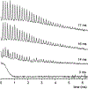
Time-domain 79Br signals of KBr as a function of switching time. Here t = 0 is counted as the time when the stator begins to move, 12 ms after the TTL pulse signaling the closure of the valve. No rotational echoes can be seen at t = 0, as the sample is spinning at 0°. 14 ms later, the sample is moving toward the magic angle. At 16 ms, the sample has reached the magic angle, but takes an additional ms to fully stabilize, as can be seen by comparing the small rotational echoes near the end of the acquisition time. 16 scans were taken to confirm that the measurement is reproducible.
Figure 14:
Figure 14:
(a) Two P nucleii showing their respective CSA tensors (b) the two P nuclei along the internuclear vector (c) the molecules align in a crystal phase (d) the lab frame shares the X-axis with the crystal frame and is inverted along the Y- and Z-axes.
Figure 15:
Figure 15:
Net CH splitting expected in SAS HETCOR spectra for oriented samples as a function of rotor angle β. The top 6 curves (above 2000 Hz splitting) are for directly bonded CH pairs: dipolar coupling constant (rigid solid) D=−23,500 Hz. The lower 6 curves (below 2000 Hz splitting) are for non-bonded CH pairs with the next strongest CH coupling: D=−2900Hz. The dashed black box shows a range of spinning angles (β > βm) for measuring attenuated dipolar couplings while measuring (J+D) rather than (J-D). Figure reprinted from [218].
Figure 16:
Figure 16:
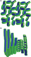
(a) Unoriented bicelle discs of the type used to solubilize membrane proteins for solution-state NMR. (b) Wormlike micelles making up a chiral nematic phase. Based on neutron scattering data [266], this is thought to be the predominant phase of the DMPC/DHPC mixtures most frequently used in aligned-sample NMR.
Figure 17:
Figure 17:
(a) A phosphorus nucleus showing its CSA tensor, (b) the 31P nucleus and its CSA in position in the head-group of the DMPC, (c) alignment of wormlike micelles showing director. (d) Wormlike micelles align with the director perpendicular to the rotor axis when the spinning angle is greater than the magic angle and parallel to the rotor axis when the spinning angle is less than the magic angle. (e) The wormlike micelles in the rotor are oriented with respect to the external magnetic field.

References

    1. Grandinetti PJ, Baltisberger JH, Llor A, Lee YK, Werner U, Eastman MA, Pines A, Pure-absorption-mode lineshapes and sensitivities in 2-dimensional dynamic angle spinning NMR, Journal of Magnetic Resonance Series A 103 (1) (1993) 72–81.
    1. Gann SL, Baltisberger JH, Pines A, Dynamic-angle spinning without sidebands, Chemical Physics Letters 210 (4–6) (1993) 405–410.
    1. Klinowski J, Spin-off for solid-state studies, Nature 346 (1990) 509–510.
    1. Grandinetti P, The Encyclopedia of NMR, Wiley, 1996, Ch. Dynamic Angle Spinnng, pp. 1768–1776.
    1. Zax DB, dynamic angle spinning and double rotation quadrupolar NMR, Trends in Analytical Chemistry 13 (8) (1994) 300–312.

Publication types

MeSH terms