. 2015 Nov;26(8):2320-4.
doi: 10.1097/SCS.0000000000001996.

Bilateral Continuous Automated Distraction Osteogenesis: Proof of Principle

Affiliations

Bilateral Continuous Automated Distraction Osteogenesis: Proof of Principle

Zachary S Peacock et al. J Craniofac Surg. 2015 Nov.

Abstract

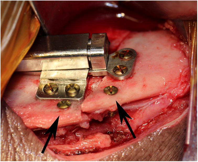
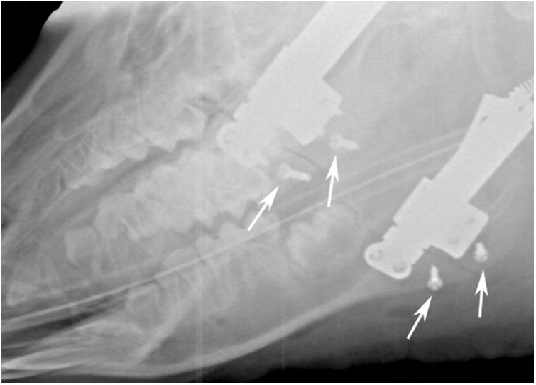
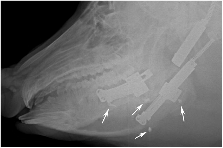
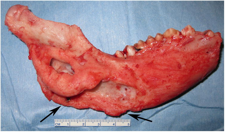
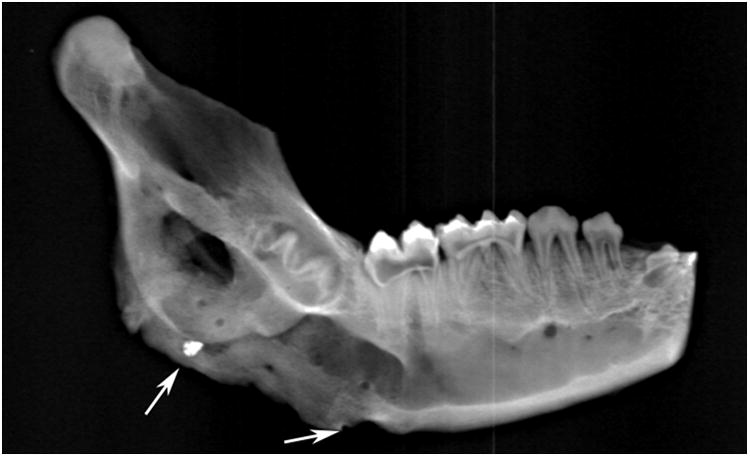
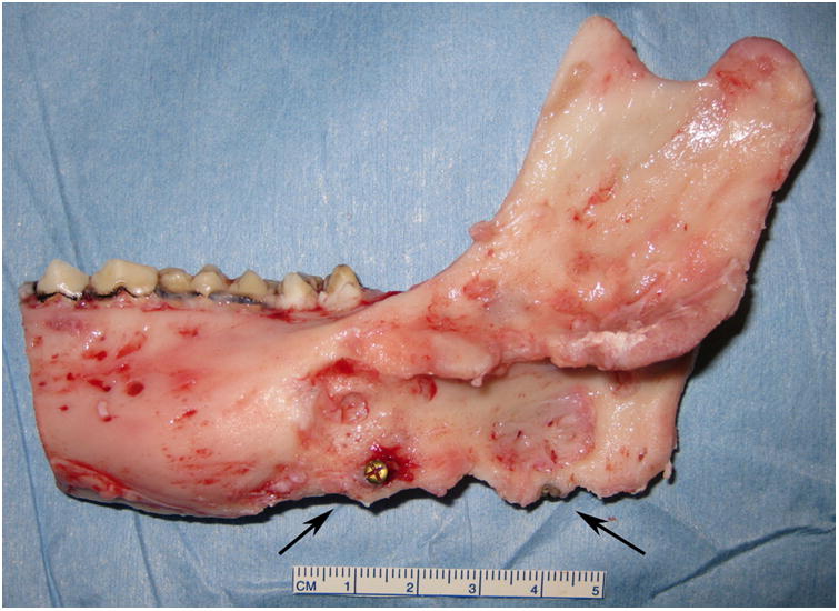
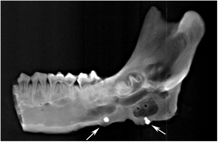
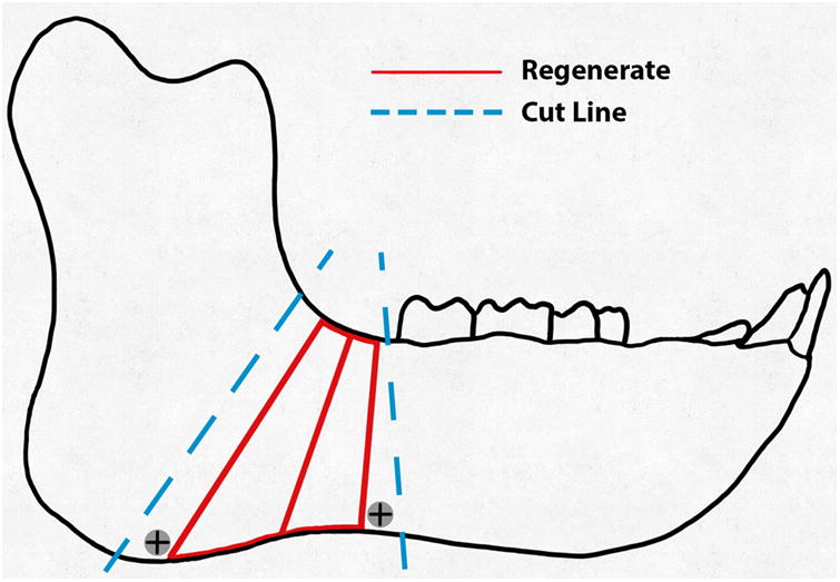
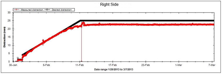
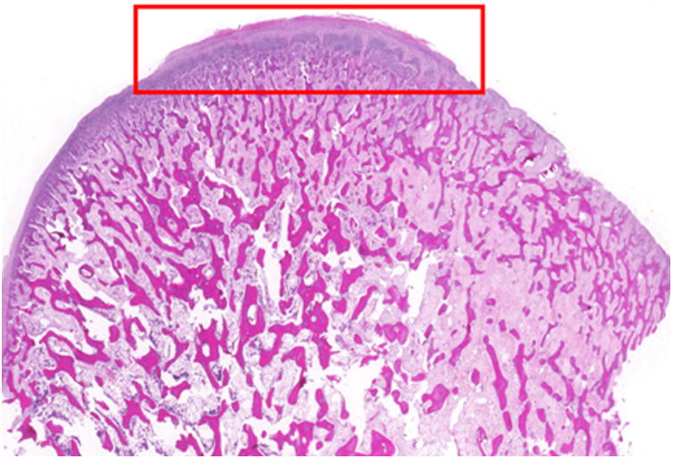
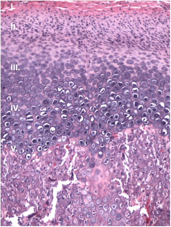
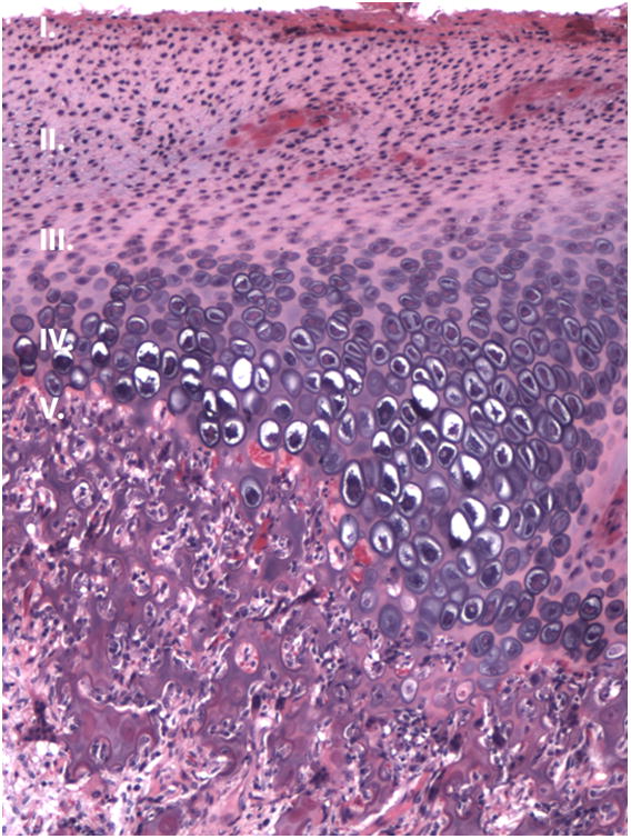
The purpose of this study was to demonstrate that automated, continuous, curvilinear distraction osteogenesis (DO) in a minipig model is effective when performed bilaterally, at rates up to 3 mm/day, to achieve clinically relevant lengthening. A Yucatan minipig in the mixed dentition phase underwent bilaterally, at a continuous DO at a rate of 2 mm/day at the center of rotation; 1.0 and 3.0 mm/day at the superior and inferior regions, respectively. The distraction period was 13 days with no latency period. Vector and rate of distraction were remotely monitored without radiographs, using the device sensor. After fixation and euthanasia, the mandible and digastric muscles were harvested. The ex vivo appearance, stability, and radiodensity of the regenerate were evaluated using a semiquantitative scale. Percent surface area (PSA) occupied by bone, fibrous tissue, cartilage, and hematoma were calculated using histomorphometrics. The effects of DO on the digastric muscles and mandibular condyles were assessed via microscopy, and degenerative changes were quantified. The animal was distracted to 21 mm and 24 mm on the right and left sides, respectively. Clinical appearance, stability, and radiodensity were scored as "3" bilaterally indicating osseous union. The total PSA occupied by bone (right = 75.53 ± 2.19%; left PSA = 73.11 ± 2.18%) approached that of an unoperated mandible (84.67 ± 0.86%). Digastric muscles and condyles showed negligible degenerative or abnormal histologic changes. This proof of principle study is the first report of osseous healing with no ill-effect on associated soft tissue and the mandibular condyle using bilateral, automated, continuous, and curvilinear DO at rates up to 3 mm/day. The model approximates potential human application of continuous automated distraction with a semiburied device.


Figures

Figure 1
Figure 1
A, Intraoperative photograph of the device fixed across the osteotomy with markers screws (arrows) placed at the inferior border. B, Immediate postoperative radiograph showing bilateral osteotomies with marker screws (white arrows) C, End-Fixation radiograph showing the lengthening of the mandible with increased distance between marker screws (white arrows). The right side distractor became unattached during the fixation period with some loss of lengthening. The left side distractor is fully extended. The regenerate appears radiodense for both sides (scores of 3).
Figure 1
Figure 1
A, Intraoperative photograph of the device fixed across the osteotomy with markers screws (arrows) placed at the inferior border. B, Immediate postoperative radiograph showing bilateral osteotomies with marker screws (white arrows) C, End-Fixation radiograph showing the lengthening of the mandible with increased distance between marker screws (white arrows). The right side distractor became unattached during the fixation period with some loss of lengthening. The left side distractor is fully extended. The regenerate appears radiodense for both sides (scores of 3).
Figure 2
Figure 2
Right side hemimandible photograph (A) and radiograph (B) showing strong clinical bone fill (score of 3) and radiodensity (score of 3) within the distraction gap. The left side hemimandible photograph (C) and radiograph (D) showed similar results (score of 3 for each). Position of marker screws marked with black arrows.
Figure 2
Figure 2
Right side hemimandible photograph (A) and radiograph (B) showing strong clinical bone fill (score of 3) and radiodensity (score of 3) within the distraction gap. The left side hemimandible photograph (C) and radiograph (D) showed similar results (score of 3 for each). Position of marker screws marked with black arrows.
Figure 3
Figure 3
A, Schematic of the hemimandible (black), regenerate (red), and the intended cuts (blue).B, Graph of projected (black line) and measured distraction (red) for the right side. The measured position closely followed the projected 2 mm/day rate and remained at 21.5 mm during the consolidation period.
Figure 3
Figure 3
A, Schematic of the hemimandible (black), regenerate (red), and the intended cuts (blue).B, Graph of projected (black line) and measured distraction (red) for the right side. The measured position closely followed the projected 2 mm/day rate and remained at 21.5 mm during the consolidation period.
Figure 4
Figure 4
Condyle histology. (H&E, sagittal view). A-B, Photomicrograph of the (A) right and (B) left condylar head showing evenly spaced trabeculae and a regular articulating surface (10× magnification). C-D, Representative images from the right (D) and left (E) condyle (200 × magnification of the red box from figure 5A) that appear similar to a normal condyle.
Figure 4
Figure 4
Condyle histology. (H&E, sagittal view). A-B, Photomicrograph of the (A) right and (B) left condylar head showing evenly spaced trabeculae and a regular articulating surface (10× magnification). C-D, Representative images from the right (D) and left (E) condyle (200 × magnification of the red box from figure 5A) that appear similar to a normal condyle.

References

    1. Codivilla A. The classic: On the means of lengthening, in the lower limbs, the muscles and tissues which are shortened through deformity 1905. Clin Orthop Relat Res. 2008;466:2903–2909. - PMC - PubMed
    1. Ilizarov GA. The principles of the Ilizarov method. Bull Hosp Jt Dis Orthop Inst. 1988;48:1–11. - PubMed
    1. Ilizarov GA. The tension-stress effect on the genesis and growth of tissues: Part II The influence of the rate and frequency of distraction. Clin Orthop Relat Res. 1989;239:263–285. - PubMed
    1. Ilizarov GA. The tension-stress effect on the genesis and growth of tissues. Part I.The influence of stability of fixation and soft-tissue preservation. Clin Orthop Relat Res. 1989;238:249–281. - PubMed
    1. Ilizarov GA. Clinical application of the tension-stress effect for limb lengthening. Clin Orthop Relat Res. 1990;250:8–26. - PubMed

Publication types