

Review
doi: 10.1016/j.nic.2015.09.001.
Epub 2015 Oct 19.
Three-Dimensional Carotid Plaque MR Imaging
Affiliations
- PMID: 26610656
- PMCID: PMC4663679
- DOI: 10.1016/j.nic.2015.09.001
Item in Clipboard
Review
Three-Dimensional Carotid Plaque MR Imaging
Neuroimaging Clin N Am.
2016 Feb.
Abstract
There has been significant progress made in 3-dimensional (3D) carotid plaque MR imaging techniques in recent years. Three-dimensional plaque imaging clearly represents the future in clinical use. With effective flow-suppression techniques, choices of different contrast weighting acquisitions, and time-efficient imaging approaches, 3D plaque imaging offers flexible imaging plane and view angle analysis, large coverage, multivascular beds capability, and even can be used in fast screening.
Keywords: 3D MR imaging; 3D MRA; 3D vessel wall imaging; Atherosclerosis imaging; Vessel wall imaging; Vulnerable plaque.
Copyright © 2016 Elsevier Inc. All rights reserved.
Figures
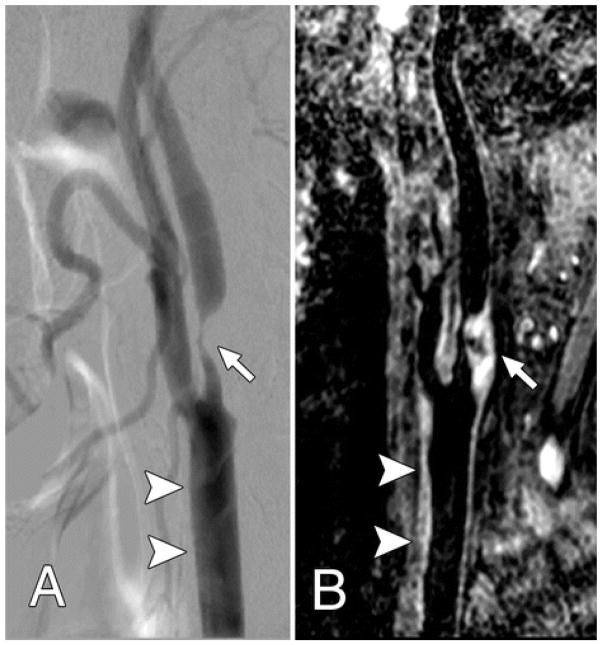
Both, A, Lateral projection DSA image and, B, oblique 3D BB MR image, show advanced atherosclerotic disease (arrow), which caused severe internal carotid artery stenosis. The common carotid artery wall thickening (arrowheads) was visualized on, B, the 3D BB MR image, but presented as normal on, A, the DSA image. From Zhao H, Wang J, Liu X, Zhao X, Hippe DS, Cao Y, Wan J, Yuan C, Xu J. Assessment of carotid artery atherosclerotic disease by using three-dimensional fast black-blood MR imaging: comparison with DSA. Radiology. 2015 Feb;274(2):508–16; with permission.
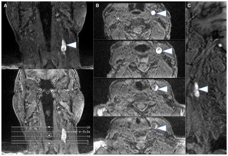
Multiplanar images (a coronal, b axial, c sagittal) of carotid intraplaque hemorrhage (arrowheads) within the wall of the left carotid artery. Intraplaque hemorrhage is detected using a 3D-T1-weighted fat-suppressed fast field echo sequence by exploiting the T1 shortening effects of methemoglobin and the technique has been histologically validated From Singh N, Moody AR, Rochon-Terry G, Kiss A, Zavodni A. Identifying a high risk cardiovascular phenotype by carotid MRI-depicted intraplaque hemorrhage. Int J Cardiovasc Imaging. 2013 Oct;29(7):1477–83; with permission.
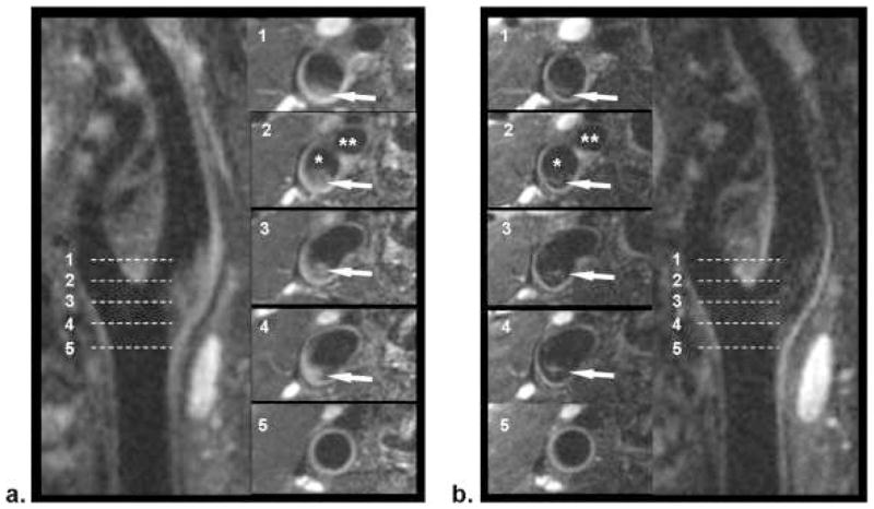
Comparison of location-matched SPACE (a) and FSD-SPACE (b) images acquired from a healthy volunteer. Using multiplanar reconstruction (MPR), both longitudinal and cross-sectional views of the carotid artery can be visualized. The FSD preparation can dramatically suppress the rb signal (arrows) shown on SPACE images, thus resulting in larger apparent lumen and higher wall-lumen contrast. The locations of the five cross-sectional images (No. 1–5) are indicated by the dashed line on the longitudinal images. *Internal carotid lumen; **external carotid lumen. From Fan Z, Zhang Z, Chung YC, et al. Carotid arterial wall MRI at 3T using 3D variable-flip-angle turbo spin-echo (TSE) with flow-sensitive dephasing (FSD). J Magn Reson Imaging. 2010 Mar;31(3):645–54. doi: 10.1002/jmri.22058; with permission.
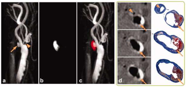
SNAP with histology confirmation. 3D MIP images of the MRA-portion (a), IPH-portion (b) and color-coded joint view (c) of the SNAP images. Both IPH and luminal MRA were nicely delineated throughout the 160 mm coverage of bilateral carotid arteries. Even small branches of the carotid artery, high-risk features like ulceration (arrows) and high-level stenosis (arrowheads) were visualized. On cross-sectional reformatted images (d), both IPH and luminal shapes were confirmed by the matched Mallory's trichrome histology slides. From Wang J, Börnert P, Zhao H, et al. Simultaneous noncontrast angiography and intraplaque hemorrhage (SNAP) imaging for carotid atherosclerotic disease evaluation. Magn Reson Med. 2013 Feb;69(2):337–45. doi: 10.1002/mrm.24254. Epub 2012 Mar 22; with permission.
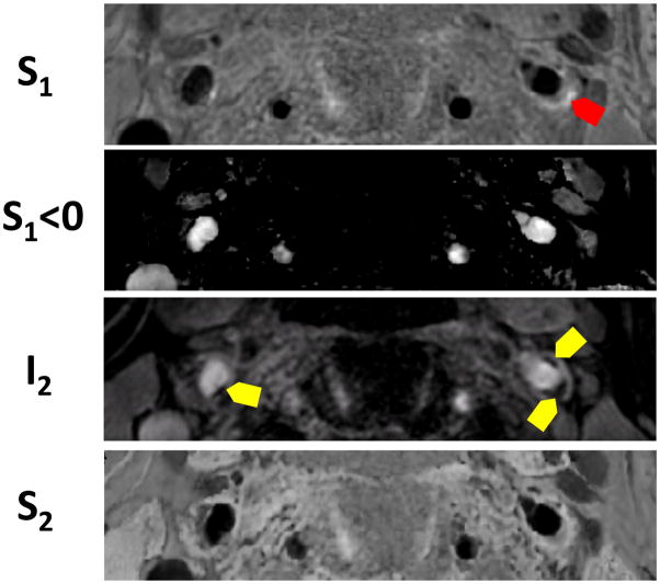
High risk plaque identification using four images reconstructed from a single sequence in a patient. Red arrows show IPH and yellow areas show juxta-luminal calcification.
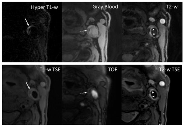
With the MATCH protocol, the unique contrast weightings and spatial coregistration facilitate easier identification of co-existent components and better appreciation of their spatial relations. The loose matrix is also hyper-intense on T1-w TSE, mimicking hemorrhage. However, it is not as hyper-intense as hemorrhage on TOF. From Fan Z, Yu W, Xie Y, Dong L, et al. J Multi-contrast atherosclerosis characterization (MATCH) of carotid plaque with a single 5-min scan: technical development and clinical feasibility. Cardiovasc Magn Reson. 2014 Jul 25;16:53. doi: 10.1186/s12968-014-0053-5; with permission.
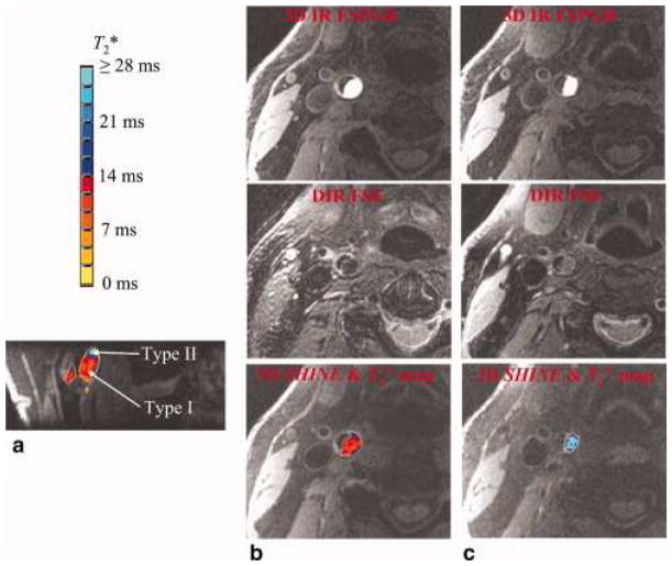
An intraplaque hemorrhage with both type I and type II hemorrhagic regions is shown. The high-contrast hemorrhagic region is clearly depicted by 3D IR FSPGR or 3D SHINE. The T*2 value is color coded with the bar at the upper-left corner. The type I hemorrhage tends to have a T*2 value below 14 msec, and type II hemorrhage tends to have a T*2 value above 14 msec. The two hemorrhage types are shown clearly in the reformatted coronal view (a). Consistent with the results from 3D SHINE, (b) type I hemorrhage (shown are axial slices at predominately type I region) appears to be hypointense in DIR FSE, and (c) type II hemorrhage (shown are axial slices at predominately type II region) appears to be iso-intense in DIR FSE. From Zhu DC1, Vu AT, Ota H, DeMarco JK. An optimized 3D spoiled gradient recalled echo pulse sequence for hemorrhage assessment using inversion recovery and multiple echoes (3D SHINE) for carotid plaque imaging. Magn Reson Med. 2010 Nov;64(5):1341–51. doi: 10.1002/mrm.22517; with permission.
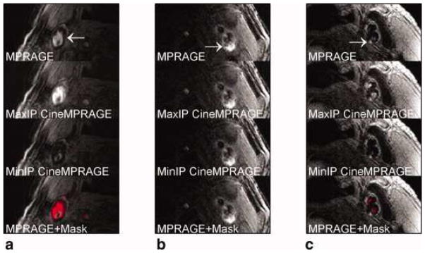
Identification of potential hemorrhage and hemorrhage mimicking flow artifacts using CineMPRAGE image reconstruction. A patient with flow artifact is shown in (a), whereas patients with potential IPH are shown in (b) and (c). The top row is the MPRAGE images reconstructed using the standard MPRAGE technique. In all cases, there are pixels with signal intensities above 1.5× sternocleidomastoid muscle. The maximum and minimum intensity projections (taken along the temporal direction) of the CineMPRAGE reconstruction are shown in the second and third rows, respectively. Although the potential hemorrhage signal is constant, the flow artifact varies across the cardiac cycle as evidenced by the difference in the maximum and minimum intensity projections. Color maps corresponding to the CineMPRAGE signal variation are overlaid on the conventional MPRAGE images on the bottom row. From Mendes J1, Parker DL, Kim SE, et al. Reduced blood flow artifact in intraplaque hemorrhage imaging using Cine MPRAGE. Magn Reson Med. 2013 May;69(5):1276–84; with permission.
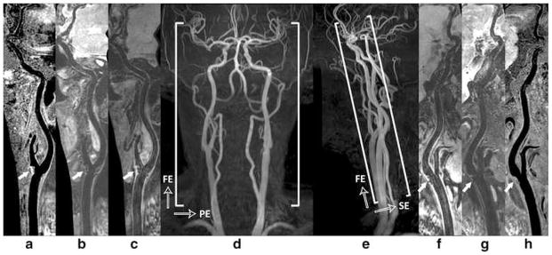
Illustration of 3D multi-contrast imaging coverage. Three stations of 3D time-of-flight coronal maximum intensity projection (MIP) fusion (d) and sagittal MIP fusion (e) are illustrated here only for a clear definition of imaging FOV. The curved multi-planar reconstruction (MPR) examples show the right (a - c) and left (f – h) sides arteries ranging from CCA through ICA to MCA, where (c, f), (b, g), and (a, h) correspond to the results of 3D-MERGE, T2-weighted VISTA and SNAP respectively. Note the plaques were detected at bilateral carotid bifurcations on all different contrast weighted images as shown by solid arrows From Zhou Z, Li R, Zhao X. Evaluation of 3D multi-contrast joint intra- and extracranial vessel wall cardiovascular magnetic resonance. J Cardiovasc Magn Reson. 2015 May 27;17:41; with permission.
Similar articles
-
Improved vessel delineation in keyhole time-resolved contrast-enhanced MR angiography using a gadolinium doped flush.J Magn Reson Imaging. 2009 May;29(5):1147-53. doi: 10.1002/jmri.21761. J Magn Reson Imaging. 2009. PMID: 19388120 Clinical Trial.
-
Novel methodology for 3D reconstruction of carotid arteries and plaque characterization based upon magnetic resonance imaging carotid angiography data.Magn Reson Imaging. 2012 Oct;30(8):1068-82. doi: 10.1016/j.mri.2012.03.004. Epub 2012 May 21. Magn Reson Imaging. 2012. PMID: 22617149
-
Nonenhanced arterial spin labeled carotid MR angiography using three-dimensional radial balanced steady-state free precession imaging.J Magn Reson Imaging. 2015 Apr;41(4):1150-6. doi: 10.1002/jmri.24640. Epub 2014 Apr 16. J Magn Reson Imaging. 2015. PMID: 24737420
-
Low-Grade Carotid Stenosis: Implications of MR Imaging.Neuroimaging Clin N Am. 2016 Feb;26(1):129-45. doi: 10.1016/j.nic.2015.09.010. Epub 2015 Oct 23. Neuroimaging Clin N Am. 2016. PMID: 26610665 Review.
-
Analysis of Multicontrast Carotid Plaque MR Imaging.Neuroimaging Clin N Am. 2016 Feb;26(1):13-28. doi: 10.1016/j.nic.2015.09.002. Neuroimaging Clin N Am. 2016. PMID: 26610657 Review.
Cited by
-
Comparison of carotid atherosclerotic plaque characteristics between symptomatic patients with transient ischemic attack and stroke using high-resolution magnetic resonance imaging.BMC Cardiovasc Disord. 2022 Apr 21;22(1):190. doi: 10.1186/s12872-022-02624-7. BMC Cardiovasc Disord. 2022. PMID: 35448952 Free PMC article.
-
Interchangeable neck shape-specific coils for a clinically realizable anterior neck phased array system.Magn Reson Med. 2017 Dec;78(6):2460-2468. doi: 10.1002/mrm.26632. Epub 2017 Feb 10. Magn Reson Med. 2017. PMID: 28185303 Free PMC article.
-
High-resolution magnetic resonance vessel wall imaging provides new insights into Moyamoya disease.Front Neurosci. 2024 Apr 11;18:1375645. doi: 10.3389/fnins.2024.1375645. eCollection 2024. Front Neurosci. 2024. PMID: 38665292 Free PMC article. Review.
-
Segment-specific progression of carotid artery atherosclerosis: a magnetic resonance vessel wall imaging study.Neuroradiology. 2020 Feb;62(2):211-220. doi: 10.1007/s00234-019-02316-8. Epub 2019 Nov 13. Neuroradiology. 2020. PMID: 31720758
-
Fabrication of Customizable Intraplaque Hemorrhage Phantoms for Magnetic Resonance Imaging.Mol Imaging Biol. 2022 Oct;24(5):732-739. doi: 10.1007/s11307-022-01722-4. Epub 2022 Apr 29. Mol Imaging Biol. 2022. PMID: 35486294 Free PMC article.
References
-
- Virmani R, Kolodgie FD, Burke AP, Finn AV, Gold HK, Tulenko TN, Wrenn SP, Narula J. Atherosclerotic plaque progression and vulnerability to rupture: angiogenesis as a source of intraplaque hemorrhage. Arterioscler Thromb Vasc Biol. 2005;25(10):2054–61. doi: 10.1161/01.ATV.0000178991.71605.18. - DOI - PubMed
-
- Saam T, Hetterich H, Hoffmann V, Yuan C, Dichgans M, Poppert H, Koeppel T, Hoffmann U, Reiser MF, Bamberg F. Meta-analysis and systematic review of the predictive value of carotid plaque hemorrhage on cerebrovascular events by magnetic resonance imaging. J Am Coll Cardiol. 2013;62(12):1081–91. doi: 10.1016/j.jacc.2013.06.015. - DOI - PubMed
-
- O'Leary DH, Polak JF. Intima-media thickness: a tool for atherosclerosis imaging and event prediction. Am J Cardiol. 2002;90(10C):18L–21L. - PubMed
Publication types
MeSH terms
Grants and funding
LinkOut - more resources
Full Text Sources
Other Literature Sources
Medical
