Review
. 2016 Jan;41(1):77-93.
doi: 10.1016/j.tibs.2015.10.009. Epub 2015 Nov 28.

Gates, Channels, and Switches: Elements of the Proteasome Machine

Affiliations
Review

Gates, Channels, and Switches: Elements of the Proteasome Machine

Daniel Finley et al. Trends Biochem Sci. 2016 Jan.

Abstract

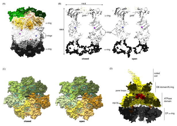
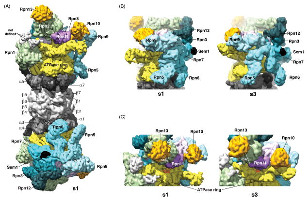
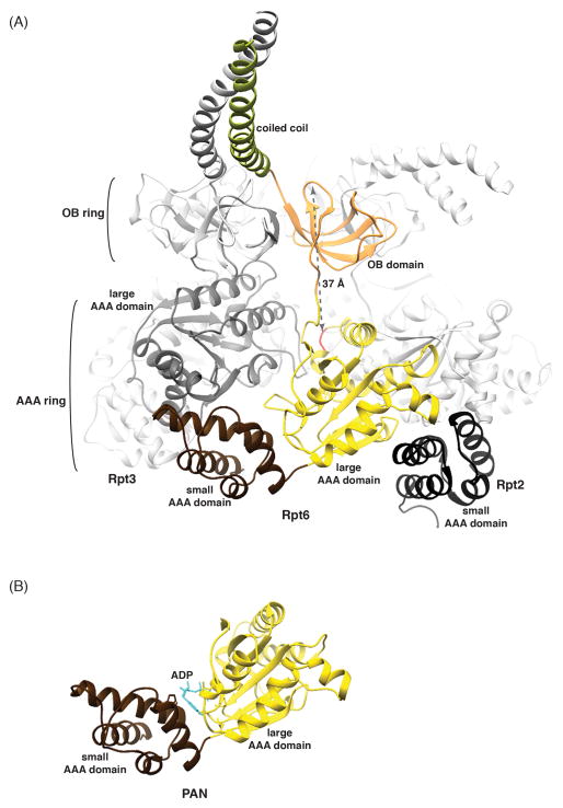
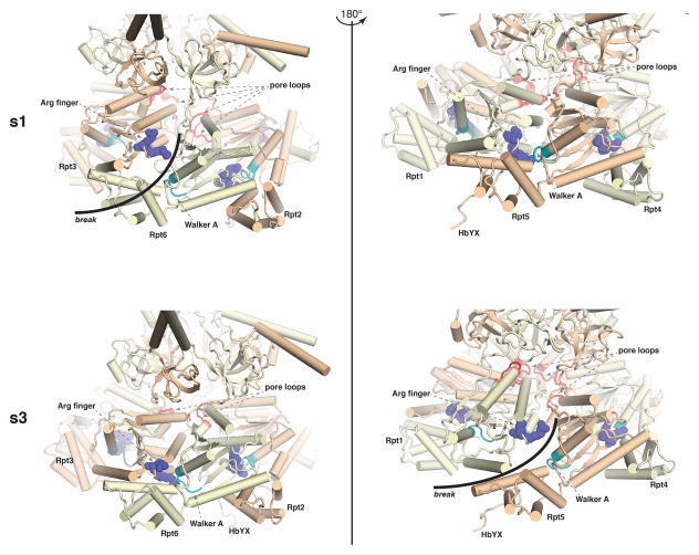
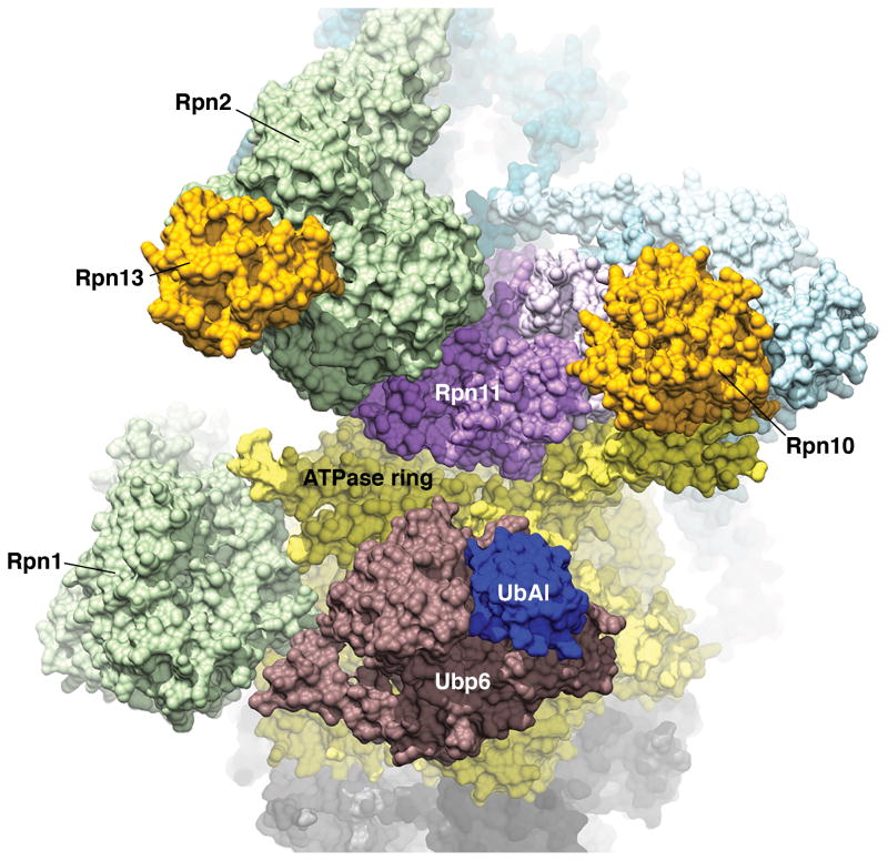
The proteasome has emerged as an intricate machine that has dynamic mechanisms to regulate the timing of its activity, its selection of substrates, and its processivity. The 19-subunit regulatory particle (RP) recognizes ubiquitinated proteins, removes ubiquitin, and injects the target protein into the proteolytic chamber of the core particle (CP) via a narrow channel. Translocation into the CP requires substrate unfolding, which is achieved through mechanical force applied by a hexameric ATPase ring of the RP. Recent cryoelectron microscopy (cryoEM) studies have defined distinct conformational states of the RP, providing illustrative snapshots of what appear to be progressive steps of substrate engagement. Here, we bring together this new information with molecular analyses to describe the principles of proteasome activity and regulation.

Keywords: ATPase; proteasome; protein degradation; ubiquitin.


Figures

Figure 1
Figure 1. Substrate entry into the core particle (CP) is gated by N-terminal tails of the α subunits
(A) A semi-transparent surface representation of the proteasome CP, generated using (PDB 1RYP) (1). For the top α-ring, ribbon diagrams are included for α-α7 and the gating residues circled. The top and bottom β-rings are distinguished by white and grey coloring respectively, and the N-terminal β1, β2, and β5 catalytic threonines rendered in blue, red, and purple, respectively. The surfaces of α-α7 and β-β7 of the top rings are transparent for visualization of the catalytic sites. (B) A cross-section of the CP in its closed (left) and open (right) state to illustrate the hollow interior and altered configuration of the N-terminal gating residues. The top α- and β-rings are rendered as ribbon diagrams whereas the bottom two rings are displayed as surfaces. The β1 and β5 catalytic sites are represented in blue and purple, respectively. Dimensions are provided for scale. (C) Top view of the α-rings for closed and open configurations of the CP. The inter-subunit clefts where C termini of many proteasome regulators dock, including the regulatory particle (RP), are circled and the gate labeled. PDB 1RYP (1) was used for the CP closed state represented in (A) – (C) whereas PDB 1FNT (2) was used for the open state in (B) and (C). The latter structure was solved in complex with the PA26 regulatory particle. (D) Surface diagram cut-away view of the CP α-ring (grey) with the RP ATPase ring (yellow) highlighting the pore loops (red), HbYX motifs (orange) and contiguous substrate entry channel. PDB 4CR4 (53) and 1FNT (2) were used to generate this image.
Figure 2
Figure 2. Cryo-electron microscopy reconstruction of the proteasome, highlighting differences in the s1 and s3 states
(A) RPs stack against each end of the CP, rotated relative to each other by ~180°. The ATPase rings (yellow) abut the α-rings (grey) of the CP with six fanned out lid components (shades of blue) lining each side of the proteasome. Sem1 binds to this area and is shown in black. In this s1 state of the proteasome, Rpn11 (purple) is offset from the center of the ATPase core. Ubiquitin receptors Rpn10 and Rpn13 (orange) are at opposite sides of Rpn11. Above Rpn1 (green) is electron density that has not yet been defined (grey), as Rpn1 model structures do not map to incorporate these two regions. (B, C) Comparative views of the s1 (left) and s3 (right) states of the proteasome. In (B) major changes are observed for Rpn6, while in (C) Rpn11 is positioned more directly over the ATPase core in the s3 configuration. Distances are included between Rpn11 A183 and Rpn13 I8 (white) and between Rpn11 S120 and Rpt1 E170 (red) to highlight conformational changes. EMD 2594 and EMD 2596 (53) were used to generate the s1 and s3 images, respectively.
Figure 3
Figure 3. The RP ATPase ring components are comprised of four structural domains with similarity to archaeal PAN
(A) The ATPase ring is displayed as a ribbon diagram highlighting the Rpt6 small (brown) and large (yellow with the pore loop red) AAA domains, OB domain (orange) and coiled coil (green). The Rpt6 small AAA domain packs against the Rpt3 large AAA domain (dark grey), while the Rpt6 large AAA domain packs against the Rpt2 small AAA domain (black). The distance between the Cα atoms of Rpt6 D118 and Y222 is included. PDB 4CR2 (53) was used for this image. (B) PAN ATPase domain with nucleotide (blue) bound between its large (yellow) and small (brown) AAA domains. The archaeal proteasome RP is formed from a PAN hexamer. PDB 3H4M (29) was used for this image.
Figure 4
Figure 4. Conformational rearrangements that reconfigure the ATPase ring in the s1 and s3 states
Expanded view in ribbon representation of the ATPase region that has a break (highlighted with a black arc) between the arginine finger (Arg finger, indigo) and Walker A motif (light blue) for the s1 (top, left) and s3 (bottom, right) configurations. These two views differ by a 180° rotation, and the corresponding view for each configuration is also included for comparison. The pore loops are highlighted in red to illustrate their transition from a spiral structure in s1 to a more planar structure in s3. HbYX motifs are labeled where visible. These images were generated from PDB accession codes 4CR2 and 4CR4 (53) for the s1 and s3 states, respectively.
Figure 5
Figure 5. Cryo-electron microscopy-based structure of the proteasome RP with deubiquitinating enzyme Ubp6-UbAl
Structure of the proteasome s2 state induced by Ubp6 (burgundy) covalently bound to ubiquitin-aldehyde (UbAl, indigo). PDB 5A5B (96) was used to generate this figure, which is colored according to Figure 2.

References

    1. Groll M, et al. Structure of 20S proteasome from yeast at 2.4 A resolution. Nature. 1997;386:463–471. - PubMed
    1. Whitby FG, et al. Structural basis for the activation of 20S proteasomes by 11S regulators. Nature. 2000;408:115–120. - PubMed
    1. Groll M, et al. A gated channel into the proteasome core particle. Nat Struct Biol. 2000;7:1062–1067. - PubMed
    1. Weber-Ban EU, Reid BG, Miranker AD, Horwich AL. Global unfolding of a substrate protein by the Hsp100 chaperone ClpA. Nature. 1999;401:90–93. - PubMed
    1. Lee C, Schwartz MP, Prakash S, Iwakura M, Matouschek A. ATP-dependent proteases degrade their substrates by processively unraveling them from the degradation signal. Mol Cell. 2001;7:627–637. - PubMed

Publication types