

On-chip assay of the effect of topographical microenvironment on cell growth and cell-cell interactions during wound healing
- PMID: 26649132
- PMCID: PMC4670448
- DOI: 10.1063/1.4936927
On-chip assay of the effect of topographical microenvironment on cell growth and cell-cell interactions during wound healing
Abstract
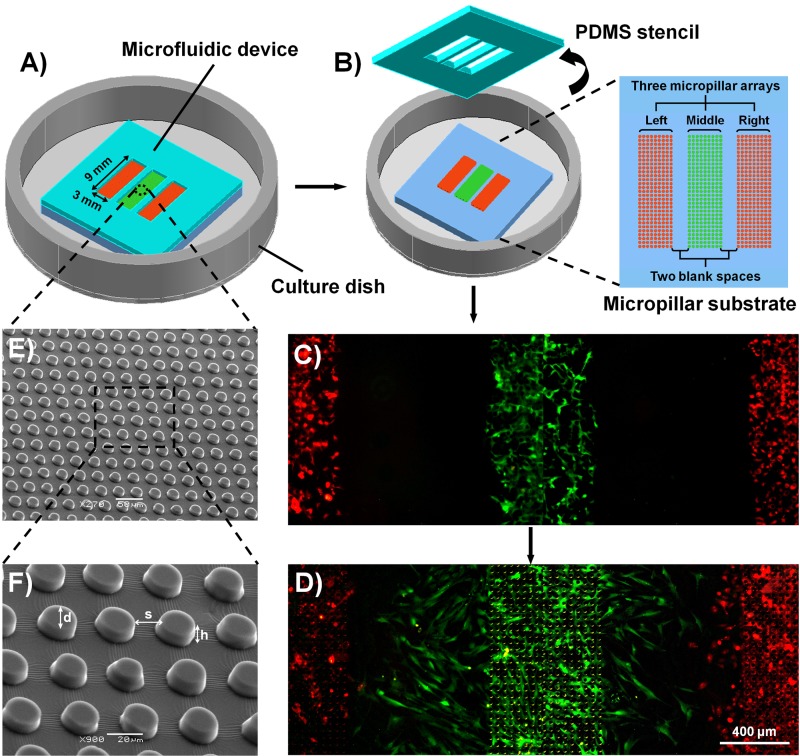
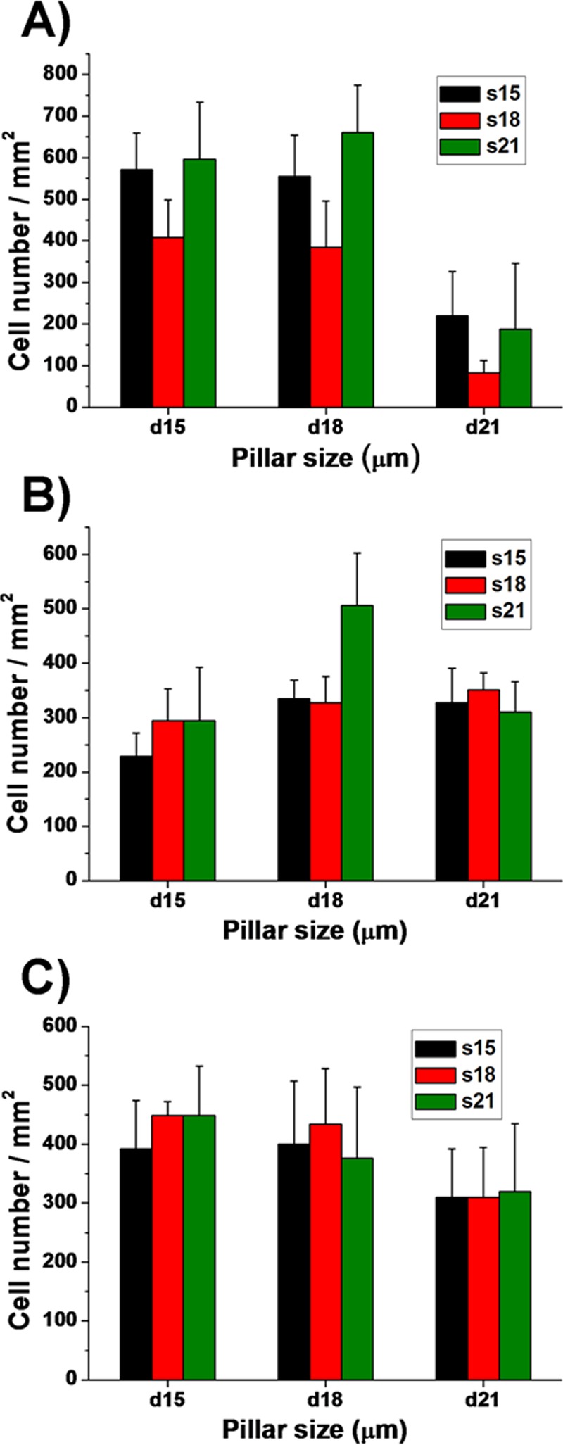
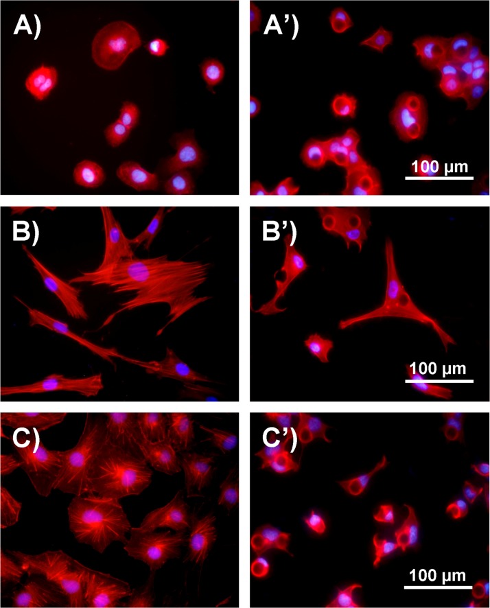
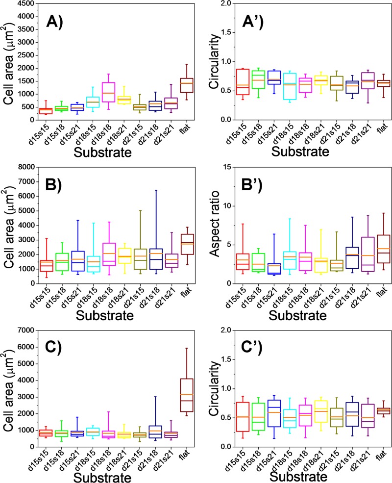
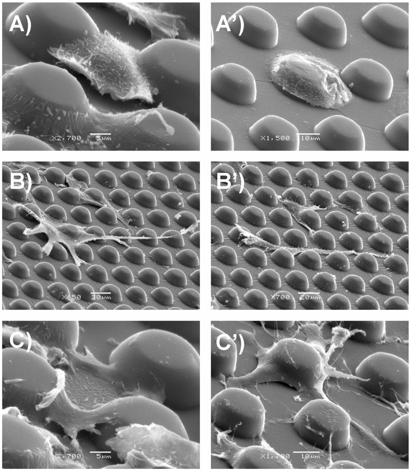
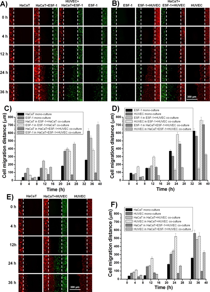
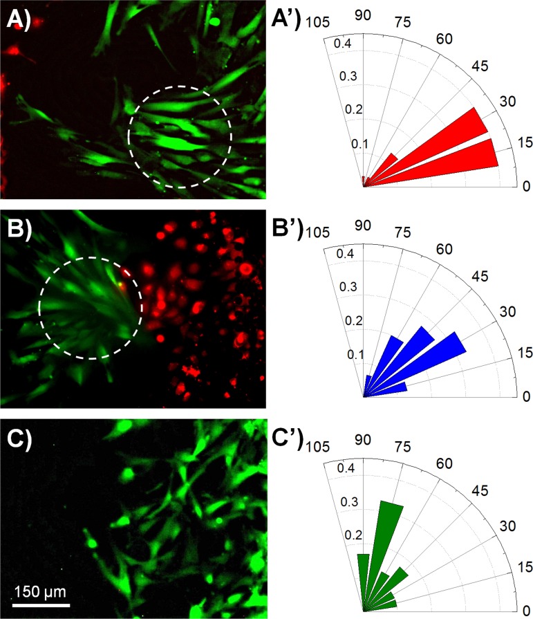
Wound healing is an essential physiological process for tissue homeostasis, involving multiple types of cells, extracellular matrices, and growth factor/chemokine interactions. Many in vitro studies have investigated the interactions between cues mentioned above; however, most of them only focused on a single factor. In the present study, we design a wound healing device to recapitulate in vivo complex microenvironments and heterogeneous cell situations to investigate how three types of physiologically related cells interact with their microenvironments around and with each other during a wound healing process. Briefly, a microfluidic device with a micropillar substrate, where diameter and interspacing can be tuned to mimic the topographical features of the 3D extracellular matrix, was designed to perform positional cell loading on the micropillar substrate, co-culture of three types of physiologically related cells, keratinocytes, dermal fibroblasts, and human umbilical vein endothelial cells, as well as an investigation of their interactions during wound healing. The result showed that cell attachment, morphology, cytoskeleton distribution, and nucleus shape were strongly affected by the micropillars, and these cells showed collaborative response to heal the wound. Taken together, these findings highlight the dynamic relationship between cells and their microenvironments. Also, this reproducible device may facilitate the in vitro investigation of numerous physiological and pathological processes such as cancer metastasis, angiogenesis, and tissue engineering.
Figures
Similar articles
-
Human lung fibroblast-derived matrix facilitates vascular morphogenesis in 3D environment and enhances skin wound healing.Acta Biomater. 2017 May;54:333-344. doi: 10.1016/j.actbio.2017.03.035. Epub 2017 Mar 27. Acta Biomater. 2017. PMID: 28351680
-
Investigation of wound healing process guided by nano-scale topographic patterns integrated within a microfluidic system.PLoS One. 2018 Jul 26;13(7):e0201418. doi: 10.1371/journal.pone.0201418. eCollection 2018. PLoS One. 2018. PMID: 30048525 Free PMC article.
-
Fabrication of microfluidic system for the assessment of cell migration on 3D micropatterned substrates.Annu Int Conf IEEE Eng Med Biol Soc. 2009;2009:6034-7. doi: 10.1109/IEMBS.2009.5333169. Annu Int Conf IEEE Eng Med Biol Soc. 2009. PMID: 19964149
-
Dermal fibroblasts-A heterogeneous population with regulatory function in wound healing.Cytokine Growth Factor Rev. 2018 Feb;39:137-150. doi: 10.1016/j.cytogfr.2018.01.003. Epub 2018 Feb 1. Cytokine Growth Factor Rev. 2018. PMID: 29395658 Review.
-
Role of keratinocyte-fibroblast cross-talk in development of hypertrophic scar.Wound Repair Regen. 2007 Sep-Oct;15 Suppl 1:S46-53. doi: 10.1111/j.1524-475X.2007.00225.x. Wound Repair Regen. 2007. PMID: 17727467 Review.
Cited by
-
3D Microstructure Inhibits Mesenchymal Stem Cells Homing to the Site of Liver Cancer Cells on a Microchip.Genes (Basel). 2017 Sep 1;8(9):218. doi: 10.3390/genes8090218. Genes (Basel). 2017. PMID: 28862651 Free PMC article.
-
Potential of CO2-laser processing of quartz for fast prototyping of microfluidic reactors and templates for 3D cell assembly over large scale.Mater Today Bio. 2021 Nov 22;12:100163. doi: 10.1016/j.mtbio.2021.100163. eCollection 2021 Sep. Mater Today Bio. 2021. PMID: 34901818 Free PMC article.
-
Bioengineered Platforms for Chronic Wound Infection Studies: How Can We Make Them More Human-Relevant?Front Bioeng Biotechnol. 2019 Dec 13;7:418. doi: 10.3389/fbioe.2019.00418. eCollection 2019. Front Bioeng Biotechnol. 2019. PMID: 31921821 Free PMC article. Review.
References
LinkOut - more resources
Full Text Sources
Other Literature Sources