. 2016 Feb 7;61(3):996-1020.
doi: 10.1088/0031-9155/61/3/996. Epub 2016 Jan 13.

4D cone-beam CT reconstruction using multi-organ meshes for sliding motion modeling

Affiliations

4D cone-beam CT reconstruction using multi-organ meshes for sliding motion modeling

Zichun Zhong et al. Phys Med Biol. .

Abstract

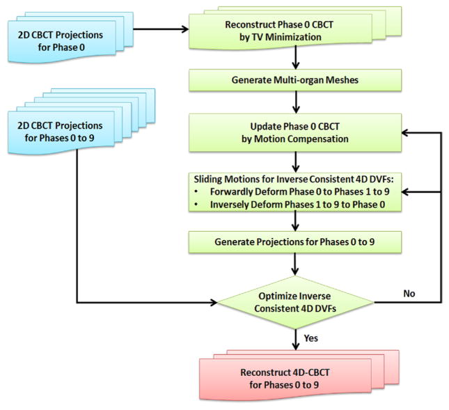
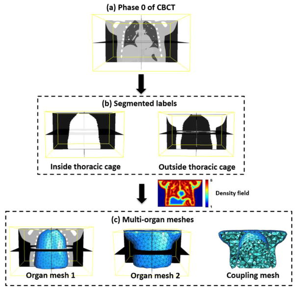
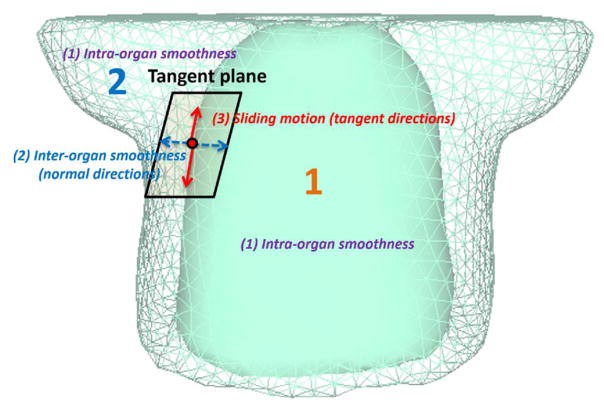
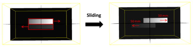
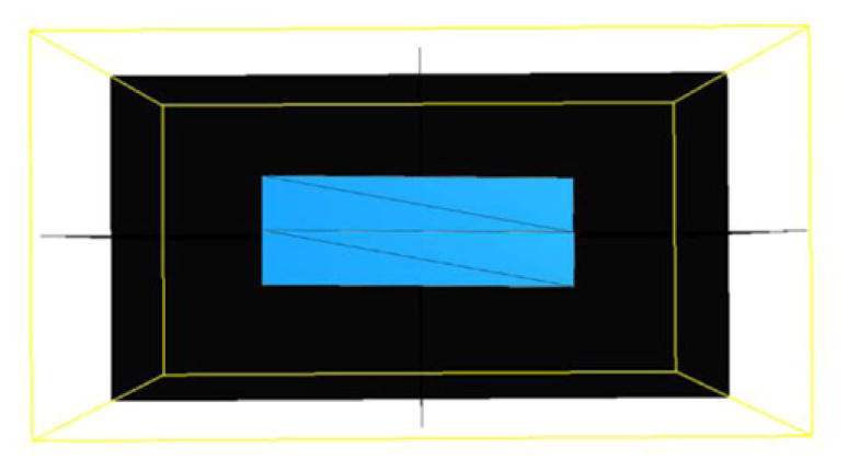
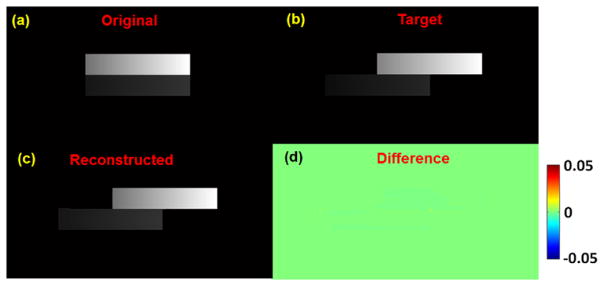
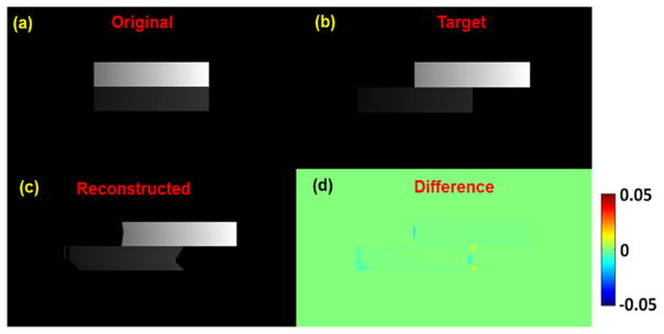
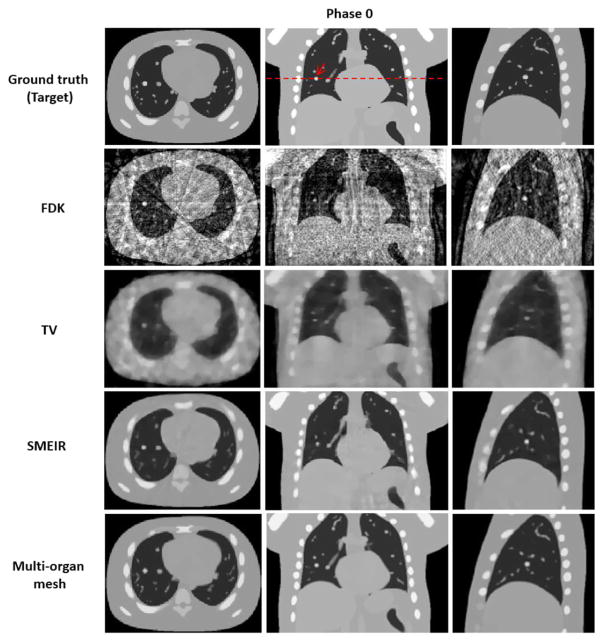
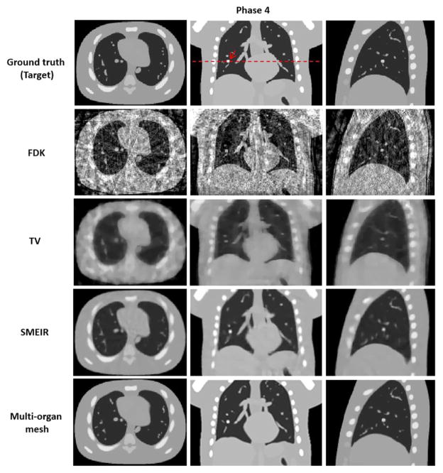
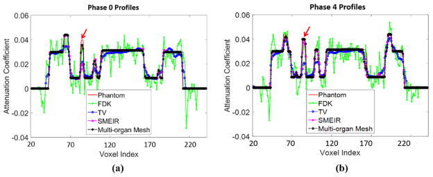
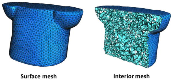
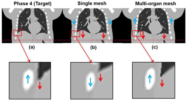
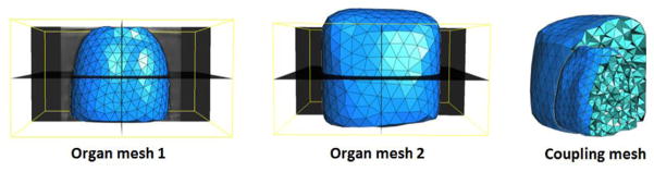
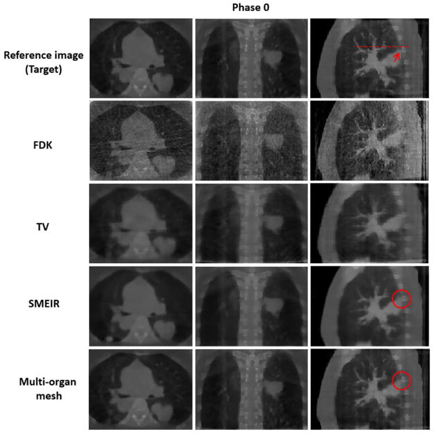
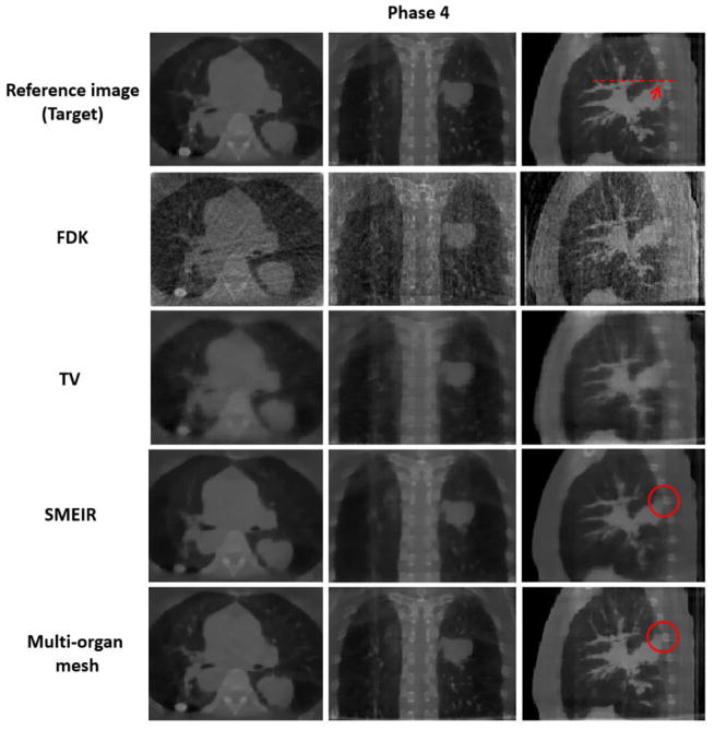
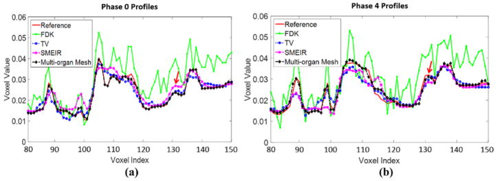
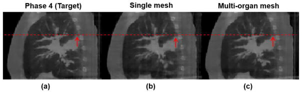
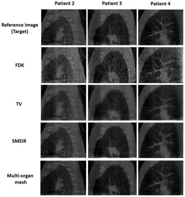
A simultaneous motion estimation and image reconstruction (SMEIR) strategy was proposed for 4D cone-beam CT (4D-CBCT) reconstruction and showed excellent results in both phantom and lung cancer patient studies. In the original SMEIR algorithm, the deformation vector field (DVF) was defined on voxel grid and estimated by enforcing a global smoothness regularization term on the motion fields. The objective of this work is to improve the computation efficiency and motion estimation accuracy of SMEIR for 4D-CBCT through developing a multi-organ meshing model. Feature-based adaptive meshes were generated to reduce the number of unknowns in the DVF estimation and accurately capture the organ shapes and motion. Additionally, the discontinuity in the motion fields between different organs during respiration was explicitly considered in the multi-organ mesh model. This will help with the accurate visualization and motion estimation of the tumor on the organ boundaries in 4D-CBCT. To further improve the computational efficiency, a GPU-based parallel implementation was designed. The performance of the proposed algorithm was evaluated on a synthetic sliding motion phantom, a 4D NCAT phantom, and four lung cancer patients. The proposed multi-organ mesh based strategy outperformed the conventional Feldkamp-Davis-Kress, iterative total variation minimization, original SMEIR and single meshing method based on both qualitative and quantitative evaluations.


Figures

Figure 1
Figure 1
Flow chart of the proposed 4D-CBCT reconstruction method by multi-organ meshes for sliding motion modeling. Blue color boxes represent the input data; green color boxes represent the main algorithm part; the red color box represents the final output data.
Figure 2
Figure 2
Demonstration of the multi-organ meshes generation on a digital 4D NCAT phantom. (a) The reference image at phase 0 of 4D-CBCT; (b) segmented label volumes; (c) multi-organ meshes well preserved the organ surfaces and image features.
Figure 3
Figure 3
Three different constraints between and inside the organs: intra-organ smoothness, inter-organ smoothness, and sliding motion.
Figure 4
Figure 4
3D synthetic sliding motion phantom.
Figure 5
Figure 5
Meshes of synthetic sliding motion phantom.
Figure 6
Figure 6
The reconstruction result of synthetic sliding motion phantom in coronal view. (a) Original image (before sliding); (b) target image (after sliding); (c) reconstructed image from the original image; (d) differences between reconstructed and target images. Display window for (a)–(c) is [0, 0.05] mm−1.
Figure 7
Figure 7
The reconstruction without inverse consistency of DVF result of synthetic sliding motion phantom in coronal view. (a) Original image (before sliding); (b) target image (after sliding); (c) reconstructed image from the original image; (d) differences between reconstructed and target images. Display window for (a)–(c) is [0, 0.05] mm−1.
Figure 8
Figure 8
Reconstructed 4D NCAT phantom at phase 0 (end-expiration) by using 4 different reconstruction algorithms with average projection numbers of 20. FDK: Feldkamp–Davis–Kress; TV: total variation. SMEIR: simultaneous motion estimation and image reconstruction. First through third columns show the transaxial, coronal, and sagittal views, respectively. Display window for all images is [0, 0.05] mm−1.
Figure 9
Figure 9
Reconstructed 4D NCAT phantom at phase 4 (end-inspiration) by using 4 different reconstruction algorithms with average projection numbers of 20. FDK: Feldkamp–Davis–Kress; TV: total variation. SMEIR: simultaneous motion estimation and image reconstruction. First through third columns show the transaxial, coronal, and sagittal views, respectively. Display window for all images is [0, 0.05] mm−1.
Figure 10
Figure 10
Horizontal profiles through the center of coronal view images at (a) phase 0 and (b) phase 4. The arrow indicates the tumor position.
Figure 11
Figure 11
Single mesh model of 4D NCAT phantom.
Figure 12
Figure 12
Demonstration of 4D NCAT at phase 4 results at coronal views. (a) Target image (phase 4); (b) reconstructed image by the single mesh method; (c) reconstructed image by the proposed multi-organ mesh method. Display window for (a)–(c) is [0, 0.05] mm−1.
Figure 13
Figure 13
Multi-organ meshes of lung cancer patient data.
Figure 14
Figure 14
Reconstructed lung cancer patient 1 at phase 0 (end-inspiration) by using 4 different reconstruction algorithms with average projection numbers of 38. FDK: Feldkamp–Davis–Kress; TV: total variation. SMEIR: simultaneous motion estimation and image reconstruction. First through third columns show the transaxial, coronal, and sagittal views, respectively. Display window for all images is [0, 0.12] mm−1.
Figure 15
Figure 15
Reconstructed lung cancer patient 1 at phase 4 (end-expiration) by using 4 different reconstruction algorithms with average projection numbers of 38. FDK: Feldkamp–Davis–Kress; TV: total variation. SMEIR: simultaneous motion estimation and image reconstruction. First through third columns show the transaxial, coronal, and sagittal views, respectively. Display window for all images is [0, 0.12] mm−1.
Figure 16
Figure 16
Horizontal profiles through the center of sagittal view images at (a) phase 0 and (b) phase 4 of lung cancer patient 1. The arrow indicates the tumor boundary close to the bone.
Figure 17
Figure 17
Demonstration of lung cancer patient 1 at phase 4 results at sagittal views. (a) Target image (phase 4); (b) reconstructed image by the single mesh method; (c) reconstructed image by the proposed multi-organ mesh method. Display window for (a)–(c) is [0, 0.12] mm−1.
Figure 18
Figure 18
Reconstructed lung cancer patient 2–4 at phase 0 (end-inspiration) at sagittal views by using 4 different reconstruction algorithms. FDK: Feldkamp–Davis–Kress; TV: total variation. SMEIR: simultaneous motion estimation and image reconstruction. First through third columns show patient 2, patient 3, and patient 4, respectively. Display window for all images is [0, 0.12] mm−1.

References

    1. Agostoni E, Zocchi L. Mechanical coupling and liquid exchanges in the pleural space. Clin Chest Med. 1998;19:241–60. - PubMed
    1. Ahn B, Kim J. Measurement and characterization of soft tissue behavior with surface deformation and force response under large deformations. Med Image Anal. 2010;14:138–48. - PubMed
    1. Berg MD, Cheong O, Kreveld MV, Overmars M. Computational Geometry: Algorithms and Applications. Berlin: Springer; 2008.
    1. Bergner F, Berkus T, Oelhafen M, Kunz P, Pa T, Grimmer R, Ritschl L, Kachelriess M. An investigation of 4D cone-beam CT algorithms for slowly rotating scanners. Med Phys. 2010;37:5044–53. - PubMed
    1. Bergner F, Berkus T, Oelhafen M, Kunz P, Pan T, Kachelriess M. Autoadaptive phase-correlated (AAPC) reconstruction for 4D CBCT. Med Phys. 2009;36:5695–706. - PMC - PubMed

Publication types