Review
. 2016 Jan 15;16(1):99.
doi: 10.3390/s16010099.

Overview of Fiber Optic Sensor Technologies for Strain/Temperature Sensing Applications in Composite Materials

Affiliations
Review

Overview of Fiber Optic Sensor Technologies for Strain/Temperature Sensing Applications in Composite Materials

Manjusha Ramakrishnan et al. Sensors (Basel). .

Abstract

This paper provides an overview of the different types of fiber optic sensors (FOS) that can be used with composite materials and also their compatibility with and suitability for embedding inside a composite material. An overview of the different types of FOS used for strain/temperature sensing in composite materials is presented. Recent trends, and future challenges for FOS technology for condition monitoring in smart composite materials are also discussed. This comprehensive review provides essential information for the smart materials industry in selecting of appropriate types of FOS in accordance with end-user requirements.

Keywords: composite materials; fiber optic sensor; smart materials; strain/temperature sensing; structural health monitoring.


Figures

Figure 1
Figure 1
(a) Use of CF composites by industry [14]; (b) GRP production in Europe for different application industries [14] and (c) development of composite aerospace applications in last 40 years (source data from Hexcel Corp. Aerostrategy).
Figure 2
Figure 2
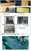
Embedding fiber sensors inside composite materials (a) hand layup; (b) pre-preg method, and (c) expert assisted manufacturing of composite part embedded with FOS.
Figure 3
Figure 3
Fiber Bragg grating.
Figure 4
Figure 4
(a) Measured wavelength shift for the FBG sensors at different deflection values (b) measured wavelength shift for the FBG sensors at different temperatures [56].
Figure 5
Figure 5
(a) Reflection spectra for an FBG written in a HB-PM-PCF with two peaks corresponding to slow axis and fast axis; (b) change in the peak separation with transverse strain for FBGs written in MOF and bow-tie type fibers; and (c) change in peak separation with temperature [60].
Figure 6
Figure 6
Spectral response of a PS-FBG and its interrogation technique based on a narrow band laser signal [61].
Figure 7
Figure 7
(a) Temperature-induced wavelength shift of the embedded polymer and silica FBGs and its comparison with free-space FBGs; (b) measured 1.5 dB bandwidth of polymer FBG and 3 dB bandwidth of silica FBG at different temperatures [65].
Figure 8
Figure 8
Wavelength shifts of the polymer and silica FBGs with deflection in the middle of the composite material [65].
Figure 9
Figure 9
(a) One of the typical EFPI sensor design; and (b) schematic experimental arrangement for the EPFI sensor [70].
Figure 10
Figure 10
(a) Experimentally measured strain using embedded EFPI sensor during three point bending test in a composite [69]; (b) Responses of the of photonic crystal fiber based sensors embedded in the composite material sample during deflections based on three point bending test [70]; and (c) at different temperatures of the composite sample [56].
Figure 11
Figure 11
Schematic of the sensor based on a Sagnac interferometer.
Figure 12
Figure 12
Responses of the HB-PM-PCF based SI sensor embedded in the composite material sample during deflections based on three point bending test [56].
Figure 13
Figure 13
(a) Experimental setup for measurements with fiber optic polarimetric sensors in intensity domain [66]; and (b) Change of the polarization of fiber optic polarimetric sensors as a function of strain applied to a composite sample [76].
Figure 14
Figure 14
Micro bend sensor concept [40].
Figure 15
Figure 15
The temporal profiles corresponding to loading (a) and optical signal attenuation (b) [40].
Figure 16
Figure 16
Strain measured by the optical fiber bonded to a composite sample for various loading conditions (data redrawn from Luna Engineering Note EN-FY1317).
Figure 17
Figure 17
Egress optical fiber with connector.
Figure 18
Figure 18
Automated optical fiber placement system (from “Airborne: the future in composites” website).

References

    1. Garg D.P., Zikry M.A., Anderson G.L., Gros X.E. Current and potential future research activities in adaptive structures: An ARO perspective. Smart Mater. Struct. 2001;10:610–623. doi: 10.1088/0964-1726/10/4/304. - DOI
    1. Balageas D. Structural Health Monitoring. ISTE; London, UK: 2006. Introduction to structural health monitoring; pp. 16–43.
    1. Cai J., Qiu L., Yuan S., Shi L., Liu P., Liang D. Composites and Their Applications. InTech; Rijeka, Croatia: 2012. Structural Health Monitoring for Composite Materials.
    1. Zhu Y.K., Gui Y.T., Rong S.L., Hong Z. A review of optical NDT technologies. Sensors. 2011;11:7773–7798. doi: 10.3390/s110807773. - DOI - PMC - PubMed
    1. Gros X.E. Current and Future Trends in Non-Destructive testing of Composite Materials. Ann. Chim. Sci. Mater. 2000;25:539–544. doi: 10.1016/S0151-9107(01)80007-6. - DOI