. 2016 Apr;13(2):026003.
doi: 10.1088/1741-2560/13/2/026003. Epub 2016 Jan 29.

Scanning electron microscopy of chronically implanted intracortical microelectrode arrays in non-human primates

Affiliations

Scanning electron microscopy of chronically implanted intracortical microelectrode arrays in non-human primates

James C Barrese et al. J Neural Eng. 2016 Apr.

Abstract

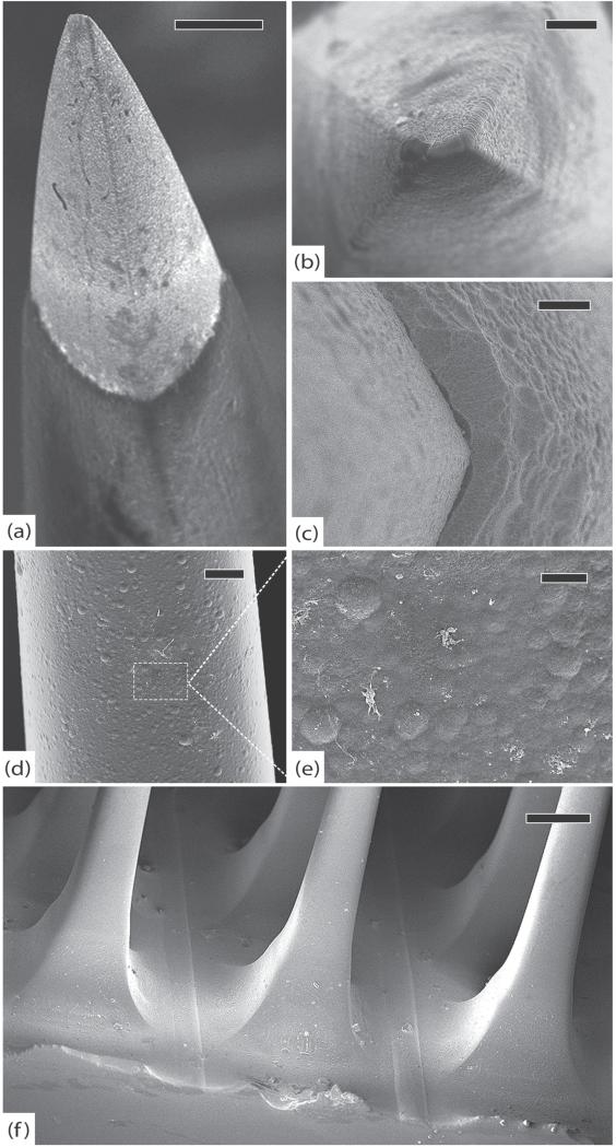
Objective: Signal attenuation is a major problem facing intracortical sensors for chronic neuroprosthetic applications. Many studies suggest that failure is due to gliosis around the electrode tips, however, mechanical and material causes of failure are often overlooked. The purpose of this study was to investigate the factors contributing to progressive signal decline by using scanning electron microscopy (SEM) to visualize structural changes in chronically implanted arrays and histology to examine the tissue response at corresponding implant sites.

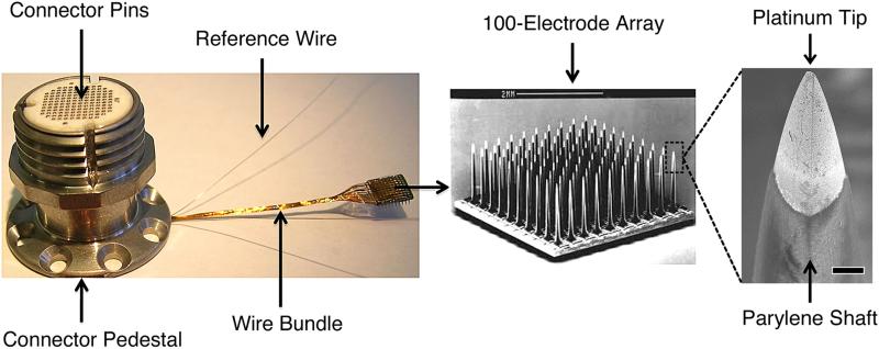
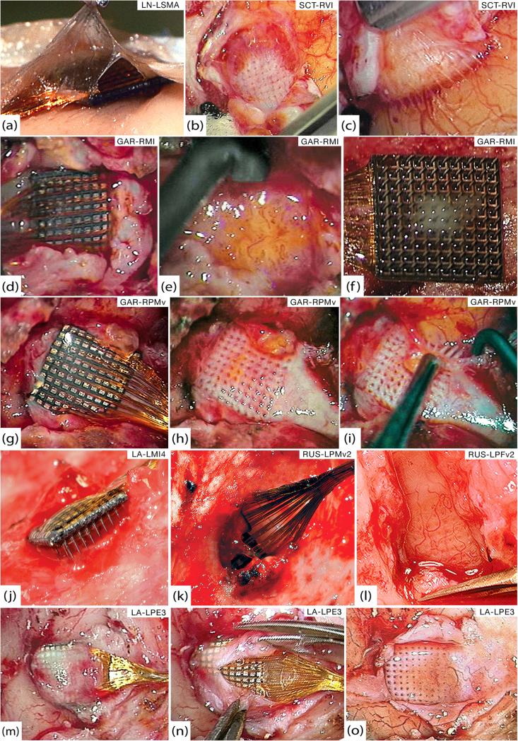
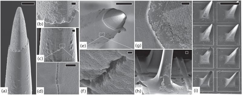
Approach: We examined eight chronically implanted intracortical microelectrode arrays (MEAs) explanted from non-human primates at times ranging from 37 to 1051 days post-implant. We used SEM, in vivo neural recordings, and histology (GFAP, Iba-1, NeuN). Three MEAs that were never implanted were also imaged as controls.

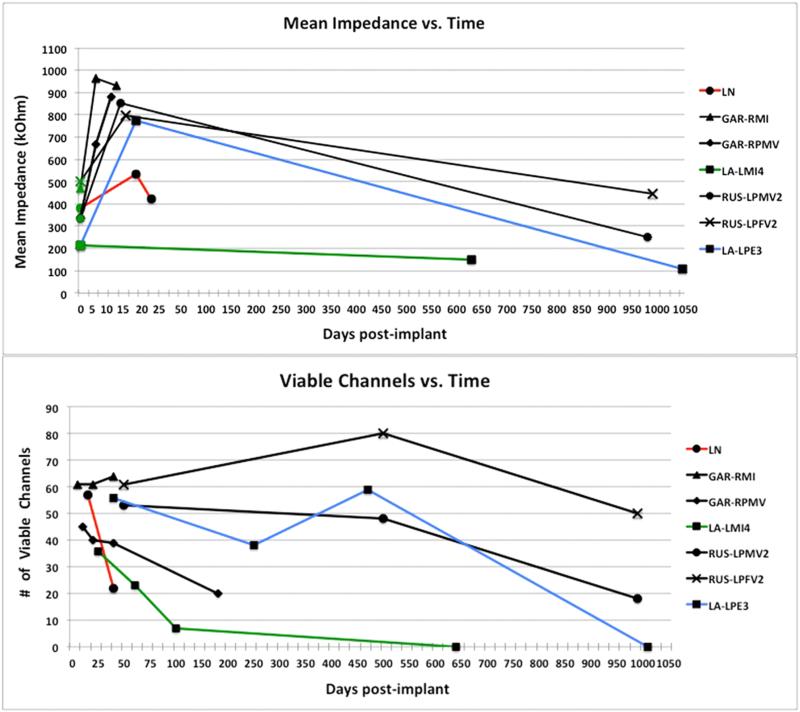
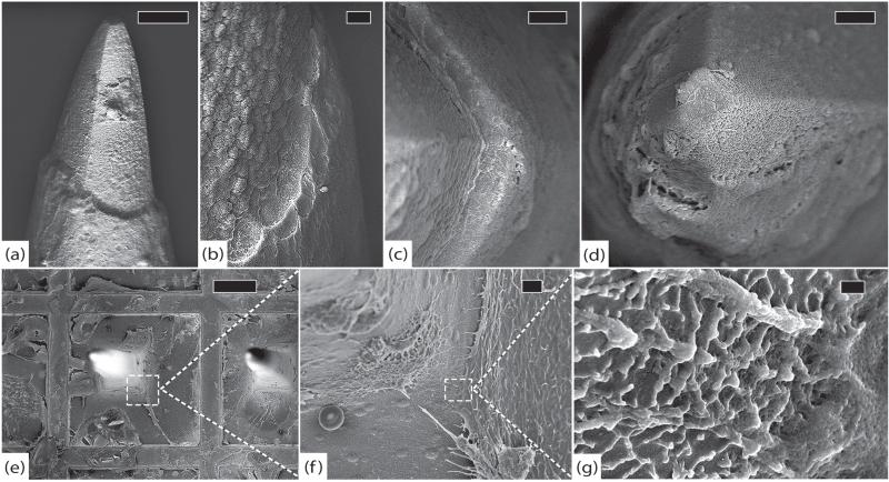
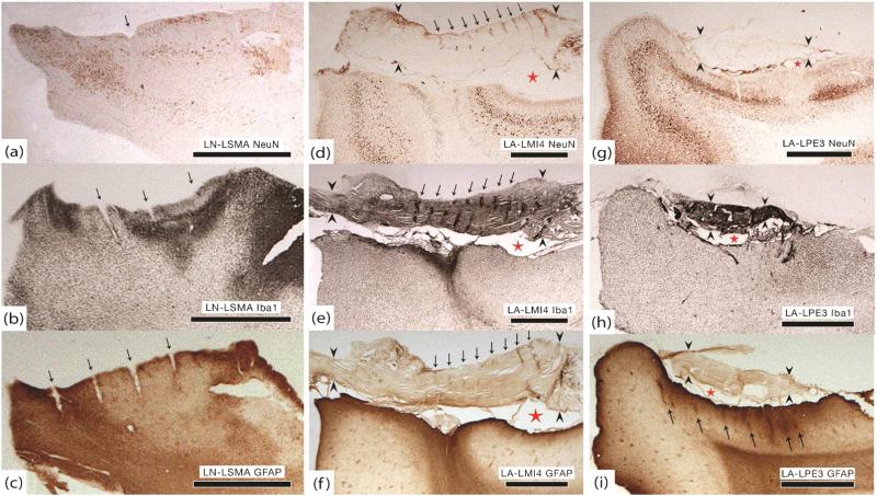
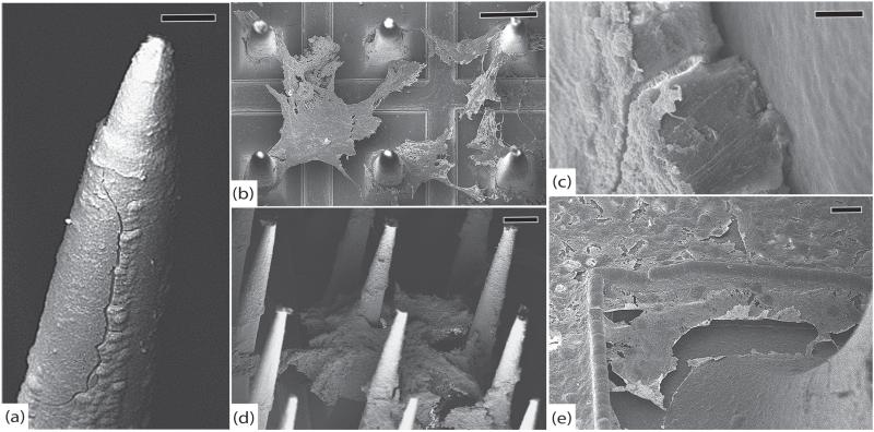
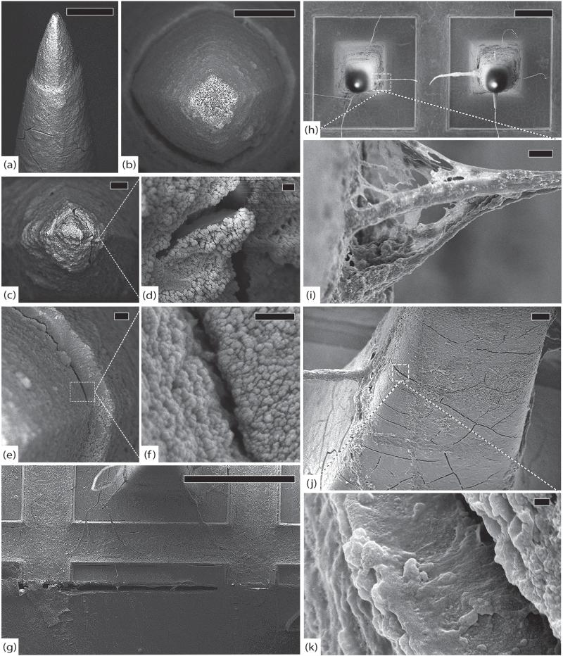
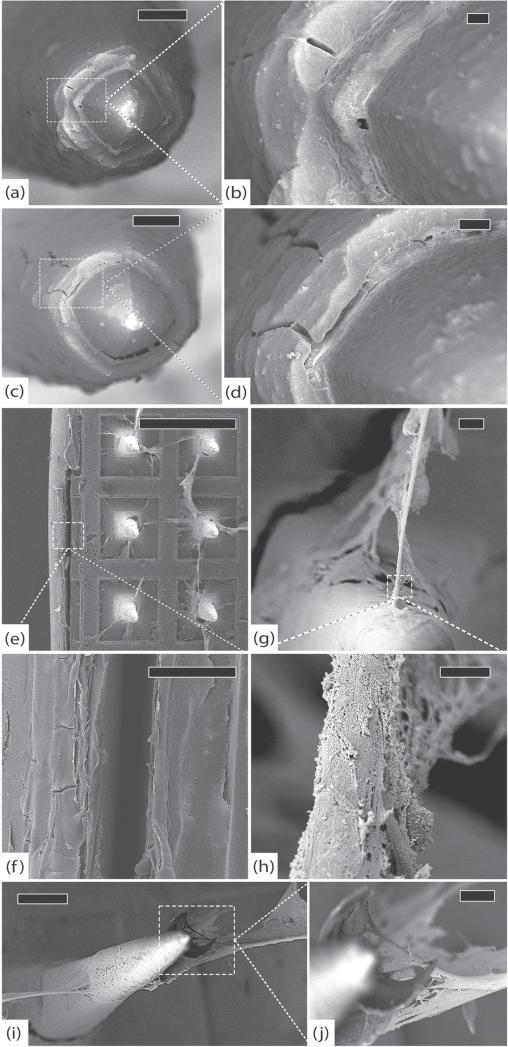
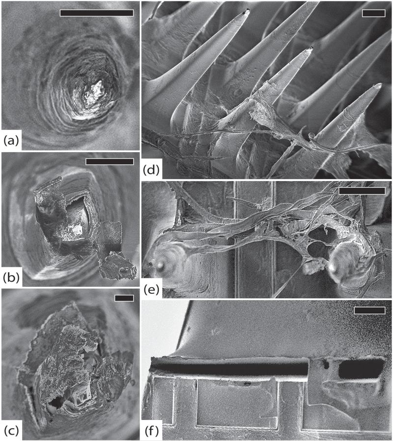
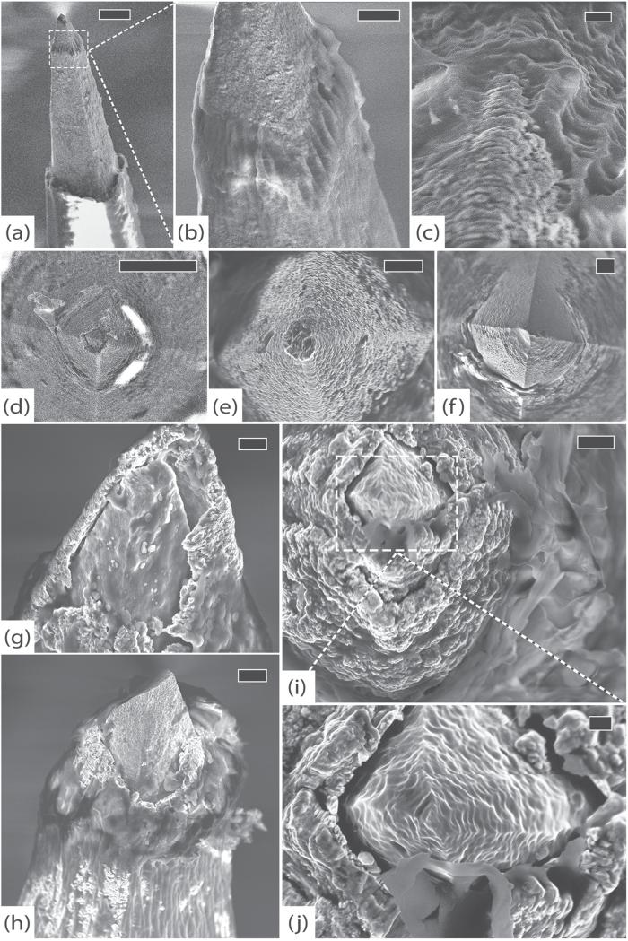
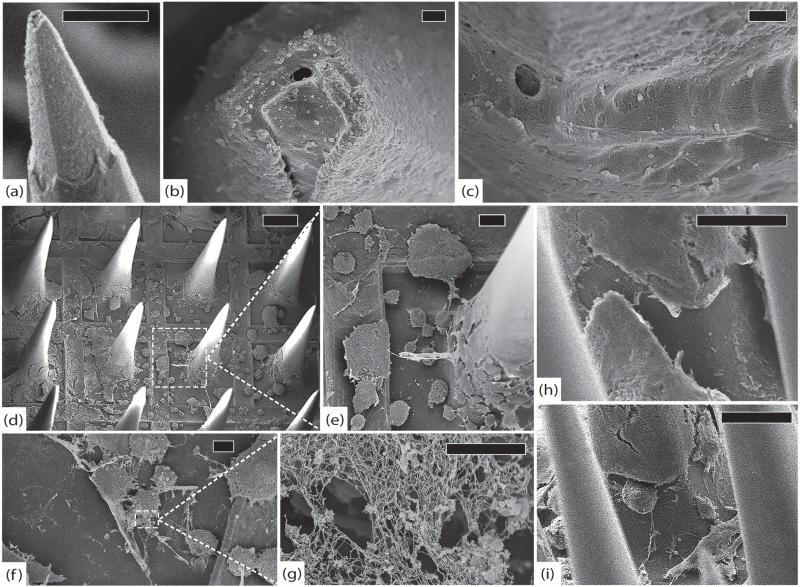
Main results: SEM revealed progressive corrosion of the platinum electrode tips and changes to the underlying silicon. The parylene insulation was prone to cracking and delamination, and in some instances the silicone elastomer also delaminated from the edges of the MEA. Substantial tissue encapsulation was observed and was often seen growing into defects in the platinum and parylene. These material defects became more common as the time in vivo increased. Histology at 37 and 1051 days post-implant showed gliosis, disruption of normal cortical architecture with minimal neuronal loss, and high Iba-1 reactivity, especially within the arachnoid and dura. Electrode tracts were either absent or barely visible in the cortex at 1051 days, but were seen in the fibrotic encapsulation material suggesting that the MEAs were lifted out of the brain. Neural recordings showed a progressive drop in impedance, signal amplitude, and viable channels over time.

Significance: These results provide evidence that signal loss in MEAs is truly multifactorial. Gliosis occurs in the first few months after implantation but does not prevent useful recordings for several years. Progressive meningeal fibrosis encapsulates and lifts MEAs out of the cortex while ongoing foreign body reactions lead to progressive degradation of the materials. Long-term impedance drops are due to the corrosion of platinum, cracking and delamination of parylene, and delamination of silicone elastomer. Oxygen radicals released by cells of the immune system likely mediate the degradation of these materials. Future MEA designs must address these problems through more durable insulation materials, more inert electrode alloys, and pharmacologic suppression of fibroblasts and leukocytes.


Figures

Figure 1
Figure 1
Blackrock Microsystem's silicon-based MEA. Left: skull-mounted titanium pedestal showing orientation of wire bundle and subdural reference electrodes. Middle: SEM of the 100-microelectrode array, scale bar is 2 mm. Right: SEM of a single electrode tip highlighting the platinum-coated silicon tip and parylene-coated silicon shaft, scale bar is 10 μm.
Figure 2
Figure 2
Gross pathology. (a) Thin encapsulation tissue of LN-LSMA at 37 days that appears continuous with both arachnoid and dura. (b) Bed of encapsulation tissue underneath SCT-RVI at 99 days. (c) Fibrous sheaths around electrode tracts penetrating the cortex from the below tissue seen in (b). (d) GAR-RMI in vivo at 554 days after overlying dura has been cut away. (e) Friable, inflamed tissue underneath GAR-RMI (f) Tissue adherent to the underside of GAR-RMI. (g) GAR-RPMv in vivo at 554 days after opening dural capsule. (h) Thick bed of encapsulation tissue underneath GAR-RPMv. (i) Thick fibrous sheaths around electrode tracts were seen diving down into the cortex as the tissue bed from (h) was reflected. (j) At 639 days, LA-LMI4 was completely encapsulated by dura and much of the array was extradural. (k) RUS-LPMv2 was entirely wrapped in dura and partially extruded from the cortex at 994 days. (l) Highly-vascularized bed of thick encapsulation tissue continuous with the dura found below RUS-LPFv2 at 994 days. (m) LA-LPE3 in vivo at 1051 days. The cut edges of the dura are visible on either side of the wire bundle and encapsulation tissue covers the array. (n) Microsurgical dissection of the capsule from (m), showing that it is more like dura than arachnoid. (o) Once the array from (n) was removed, a thick bed of encapsulation tissue was seen below and was clearly continuous with the dura.
Figure 3
Figure 3
Neural recordings. Top: mean impedance (kOhm) over time (days post-implant). Initial (pre-implant) values are plotted at day 0 with green markers. Scale for the first 50 days is expanded to show the early rise in impedance. Bottom: the number of viable channels on each array over time (days post-implant). Failure modes are indicated by line color. Red = acute biological, blue = chronic unknown, green = chronic biological, black = acute mechanical.
Figure 4
Figure 4
Control arrays. (a) Control array 1 (CA1), representative tip showing platinum/parylene border, scale 10 μm. (b) CA1, another normal tip showing pyramidal geometry of electrodes, scale 2 μm. (c) Control array 2 (CA2), normal platinum/parylene interface without delamination, scale 1 μm. (d) Control array 3 (CA3), normal appearance of parylene along an electrode shaft, scale 10 μm. (e) Close-up of parylene surface from (d) showing characteristic surface irregularities, scale 2 μm. (f) CA3, edge of the array, note that there is no silicone elastomer on this array and there are no cracks in the parylene, scale 100 μm. All images in this figure were taken at 5 kV.
Figure 5
Figure 5
LN-LSMA, 37 days (a) electrode tip with thin film of encapsulation tissue, scale 10 μm. (b) Platinum/parylene interface without delamination, scale 1 μm. (c) The platinum/parylene interface of another electrode at a different angle showing no significant delamination and a thin layer of fibrosis, scale 2 μm. (d) Intact platinum electrode tip partially covered with encapsulation tissue approx. 250 nm thick, scale 2 μm. (e) Active macrophages and fibroblasts along the base of the array, scale 100 μm. (f) Close-up at base of electrode from (e) showing active tissue growth (and an erythrocyte), scale 5 μm. (g) Higher magnification of encapsulation tissue from (f) showing individual collagen fibers, scale 200 nm. All images in this figure were taken at 5 kV.
Figure 6
Figure 6
Histology. All sections were prepared in the coronal plane. Black arrows point to electrode tracts, red stars indicate the subarachnoid space, and black arrowheads bracket the dura. (a) LN-LSMA. Decreased NeuN staining within implant site. This may be an artifact because the entire specimen was poorly stained, including areas far from the implant site. (b) LN-LSMA. Clear region of increased Iba1 activity within implant site. (c) LN-LSMA. Increased GFAP staining at the edges of the implant site. The dura and arachnoid were not preserved and therefore they are not visible in panels (a)–(c). (d) LA-LMI4. Significant decrease in NeuN staining and loss of normal cortical architecture. (e) LA-LMI4. Dense Iba1 activity at the center of the implant site and within dural encapsulation tissue, especially around electrode tracts (black arrows). (f) LA-LMI4. Increased GFAP staining and a dense glial scar at the center of the implant site. No evidence of electrode tracts in the cortex although they are seen in the dura (black arrows). (g) LA-LPE3. Only a small region of decreased NeuN staining within the implant site. (h) LA-LPE3. Dense Iba1 activity within arachnoid and dura (black arrowheads). Increased activity within the implant site at the same location where neuronal density was diminished. (i) LA-LPE3. A thick layer of gliosis is present throughout the implant site and partial electrode tracts are identified (black arrows). The densest region of GFAP staining correlates to high Iba1 and low NeuN staining. All scale bars in this figure are 2 mm.
Figure 7
Figure 7
SCT-RVI, 99 days. (a) Representative electrode tip, scale 20 μm. (b) Detail of electrode from (a) showing intact platinum and no delamination at the parylene interface, scale 2 μm. (c) Closer view of electrode from (a) showing longitudinal cracks in the parylene, scale 2 μm. (d) Detail of parylene crack, scale 2 μm. (e) Another typical electrode with intact platinum and minimal encapsulation, scale 20 μm. (f) Detail of cracked parylene, scale 300 nm. (g) Closer view of parylene interface showing early delamination and a thin veil of encapsulation tissue, scale 1 μm. (h) Base of an electrode with fibroblasts along the shaft. There is a distinct layer of encapsulation tissue creeping up the electrode, scale 20 μm. (i) Globular macrophages and spindle-shaped fibroblasts are visible on the base of the array, scale 300 μm. All images in this figure were taken at 5 kV.
Figure 8
Figure 8
GAR-RMI, 554 days. (a) Side view of an electrode with a large longitudinal crack in the parylene adjacent to surface irregularities, scale 20 μm. (b) Top view of array showing sheets of fibrosis suspended between electrodes, scale 200 μm. (c) Cracked parylene along an electrode shaft with underlying silicon exposed and tissue invasion, scale 1 μm. (d) Side view of the array showing thick fibrous tissue suspended between electrodes. Note that the tissue is adherent halfway up the shaft, indicating that the electrode tips were not fully seated in the cortex, scale 100 μm. (e) A thin film of collagen is present along the base of the array. A crack in the parylene is also visible underneath this encapsulation tissue, scale 10 μm. All images in this figure were taken at 5 kV.
Figure 9
Figure 9
GAR-RPMv, 554 days. (a) Side view of a typical electrode with intact platinum, cracked parylene and substantial fibrosis, scale 20 μm. (b) Top view of another typical electrode with intact platinum and thick, uniform fibrous encapsulation, scale 10 μm. (c) An electrode tip with thick encapsulation tissue, scale 3 μm. (d) Detail of cracked platinum tip, scale 200 nm. (e) Delaminating parylene interface, scale 1 μm. (f) Detail of parylene delamination, scale 200 nm. (g) Edge of the array showing silicone elastomer peeling away from parylene, scale 200 μm. (h) Top view of array showing large collagen fibers suspended between electrodes, scale 100 μm. (i) Detail of elastic collagen fiber attached to the shaft of an electrode, scale 3 μm. (j) An electrode shaft showing adherent elastic collagen fiber and abundant cracks in parylene, scale 10 μm. (k) Detail of a full-thickness transverse crack in parylene with tissue invasion, scale 200 nm. All images in this figure were taken at 5 kV.
Figure 10
Figure 10
LA-LMI4, 639 days. (a) Typical electrode tip with intact platinum and thick encapsulation, scale 10 μm, 3 kV. (b) Detail of parylene interface where a longitudinal crack is seen but delamination cannot be assessed because the interface is obscured by fibrosis, scale 1 μm, 3 kV. (c) Another electrode with intact platinum and clear delamination, scale 10 μm, 3 kV. (d) Detail showing cracked parylene and delamination with tissue invasion, scale 2 μm, 3 kV. (e) Silicone delaminating from parylene at the edge of the array, scale 500 μm, 8 kV. (f) Detail of silicone delamination and thin film of fibrosis on the base, scale 50 μm, 8 kV. (g) Elastic collagen fibers attached to the shaft of an electrode, scale 10 μm, 3 kV. (h) Detail of collagen fiber showing individual collagen fibrils, scale 2 μm, 3 kV. (i) Inter-electrode fibrosis peeling parylene off the electrode shaft, scale 100 μm, 3 kV. (j) Detail of collagen fibers enveloping a segment of parylene, pulling it away from the electrode, scale 20 μm, 3 kV.
Figure 11
Figure 11
RUS-LPMv2, 994 days. (a) An electrode tip completely covered in a thick layer of fibrosis, scale 20 μm. (b) Another electrode showing platinum peeling off of underlying silicon. Encapsulation tissue is intermingled with platinum fragments and there are linear defects in the platinum. These findings may be due to mechanical shearing as the array was removed from the brain, scale 10 μm. (c) An electrode with thick encapsulation tissue adherent to platinum that has separated from the silicon, scale 2 μm. (d) Side view of the array showing thick encapsulation tissue, inter-electrode fibrosis, elastic collagen fibers, and cracked parylene, scale 100 μm. (e) Thick tangle of elastic collagen fibers between electrodes in the center of the array, scale 100 μm. (f) Separation between the silicone elastomer of the wire bundle and the parylene at the edge of the array, scale 100 μm. All images in this figure were taken at 1 kV.
Figure 12
Figure 12
RUS-LPFv2, 994 days. (a) An electrode with significant delamination at parylene interface and thick fibrosis at the tip, scale 10 μm, 10 kV. (b) Detail of encapsulation showing individual collagen fibers, scale 3 μm, 10 kV. (c) Top view of another electrode showing collagenous tissue growth (top) along platinum tip (bottom), scale 300 nm, 5 kV. (d) Top view of an electrode with damaged platinum tip and exposed silicon, scale 10 μm, 5 kV. (e) Top view of another electrode with an essentially intact platinum tip, scale 2 μm, 5 kV. (f) Top view of a severely degraded electrode tip. The platinum is almost completely disintegrated and the silicon beneath it shows signs of pitting corrosion. Note that there is no evidence of mechanical damage, indicating a chronic process, scale 2 μm, 5 kV. (g) Side view of yet another electrode with severe platinum corrosion, exposure of underlying silicon, and tissue invasion, scale 1 μm, 5 kV. (h) An electrode with thick fibrous encapsulation that appears to be peeling the platinum away from the exposed silicon, scale 2 μm, 5 kV. (i) Top view of a different electrode showing a swollen, possibly oxidized, platinum layer that has separated from the underlying silicon, scale 1 μm, 5 kV. (j) Detail of tissue growth between the exposed silicon and platinum, scale 200 nm, 5 kV.
Figure 13
Figure 13
LA-LPE3, 1051 days. (a) A typical electrode tip with thick encapsulation and minimal platinum tip degradation, scale 30 μm, 8 kV. (b) Top view of another electrode tip showing platinum erosion, silicon exposure, and tissue invasion, scale 1 μm, 5 kV. (c) Top view of parylene interface where delamination is difficult to assess because of thick fibrosis, scale 1 μm, 5 kV. (d) Top view of array showing abundant cellular material and thick fibrotic encapsulation, scale 200 μm, 5 kV. (e) Detail showing numerous cells at the base of an electrode with remnants of larger inter-electrode collagen fibers, scale 30 μm, 5 kV. (f) Close-up of fibroblasts on the base, scale 10 μm, 5 kV. (g) Detail showing individual collagen fibrils that compose encapsulation tissue, scale 2 μm, 5 kV. (h) Side view of an electrode shaft with thick fibrotic encapsulation tissue, scale 70 μm, 8 kV. (i) Side view of another electrode with fibroblasts actively depositing collagen, scale 100 μm, 8 kV.

Similar articles

Cited by

References

    1. Hochberg LR, Donoghue JP. Sensors for brain–computer interfaces. IEEE Eng. Med. Biol. Mag. 2006;25:32–8. - PubMed
    1. Hochberg LR, Serruya MD, Friehs GM, Mukand JA, Saleh M, Caplan AH, Branner A, Chen D, Penn RD, Donoghue JP. Neuronal ensemble control of prosthetic devices by a human with tetraplegia. Nature. 2006;442:164–71. - PubMed
    1. Donoghue JP. Connecting cortex to machines: recent advances in brain interfaces. Nat. Neurosci. 2002;5:1085–8. - PubMed
    1. Donoghue JP, Nurmikko A, Black M, Hochberg LR. Assistive technology and robotic control using motor cortex ensemble-based neural interface systems in humans with tetraplegia. J. Physiol. 2007;579:603–11. - PMC - PubMed
    1. Kim S-P, Simeral JD, Hochberg LR, Donoghue JP, Black MJ. Neural control of computer cursor velocity by decoding motor cortical spiking activity in humans with tetraplegia. J. Neural. Eng. 2008;5:455–76. - PMC - PubMed