. 2016 Feb 3;11(2):e0147399.
doi: 10.1371/journal.pone.0147399. eCollection 2016.

Open-Source Selective Laser Sintering (OpenSLS) of Nylon and Biocompatible Polycaprolactone

Affiliations

Open-Source Selective Laser Sintering (OpenSLS) of Nylon and Biocompatible Polycaprolactone

Ian S Kinstlinger et al. PLoS One. .

Abstract

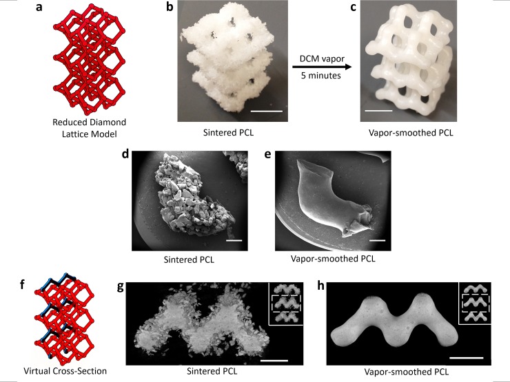
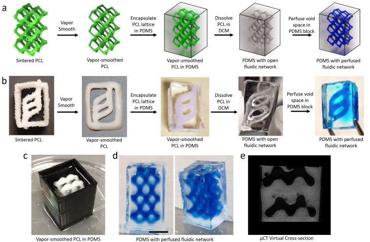
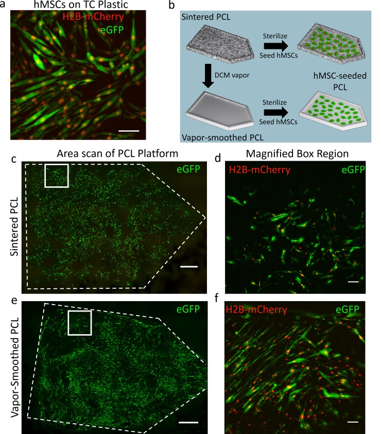
Selective Laser Sintering (SLS) is an additive manufacturing process that uses a laser to fuse powdered starting materials into solid 3D structures. Despite the potential for fabrication of complex, high-resolution structures with SLS using diverse starting materials (including biomaterials), prohibitive costs of commercial SLS systems have hindered the wide adoption of this technology in the scientific community. Here, we developed a low-cost, open-source SLS system (OpenSLS) and demonstrated its capacity to fabricate structures in nylon with sub-millimeter features and overhanging regions. Subsequently, we demonstrated fabrication of polycaprolactone (PCL) into macroporous structures such as a diamond lattice. Widespread interest in using PCL for bone tissue engineering suggests that PCL lattices are relevant model scaffold geometries for engineering bone. SLS of materials with large powder grain size (~500 μm) leads to part surfaces with high roughness, so we further introduced a simple vapor-smoothing technique to reduce the surface roughness of sintered PCL structures which further improves their elastic modulus and yield stress. Vapor-smoothed PCL can also be used for sacrificial templating of perfusable fluidic networks within orthogonal materials such as poly(dimethylsiloxane) silicone. Finally, we demonstrated that human mesenchymal stem cells were able to adhere, survive, and differentiate down an osteogenic lineage on sintered and smoothed PCL surfaces, suggesting that OpenSLS has the potential to produce PCL scaffolds useful for cell studies. OpenSLS provides the scientific community with an accessible platform for the study of laser sintering and the fabrication of complex geometries in diverse materials.


Conflict of interest statement

Competing Interests: The authors have declared that no competing interests exist.

Figures

Fig 1
Fig 1. Custom Open-source Selective Laser Sintering (OpenSLS) hardware.
a) A simplified depiction of the SLS process illustrates the sintering of powdered materials into 3D parts using a laser. For each new layer, the powder reservoir piston moves up to expose a layer of fresh powder while the build platform lowers within the build volume to leave space for the new powder layer at the top. The distributor pushes the exposed powder from the reservoir to the top of the build area so that the laser can pattern the next layer. b) A schematic rendering of our custom powder handling module. All of the red parts are 3D printed; full designs for these and the laser-cut acrylic walls may be found on the OpenSLS github repository. With the exception of the blue-green wall in the background, the exterior acrylic walls (as well as the exit ducts for excess powder) have been omitted for clarity. c) A photograph of the assembled powder module that was used throughout this study shows the components highlighted in the schematic (b) as well as the remaining acrylic walls and ducting for excess powder. The powder module was readily integrated into a commercial laser cutter with the indicated mounting brackets. d) After mounting the powder module in the laser cutter, we successfully implemented selective laser sintering and fabricated structures such as the illustrated gear. The gear is shown just after sintering and powder removal as well as after cleaning with compressed air (inset).
Fig 2
Fig 2. Complex geometries fabricated in nylon with OpenSLS.
a) Two representative models were sintered in nylon (mean particle size = 46 ± 20 μm, see S1 Fig) with 150 μm layer height, resulting in reproduction of the features and dimensions of the original geometry (scale bars = 1 cm). b) SEM imaging showed a smooth surface, partially covered by unfused nylon particles (160x magnification, scale bars = 100 μm). Inset for b) Lower magnification SEM images of structures with white box around the magnified region (scale bars = 1 mm). c) Microcomputed tomography (μCT) scans reveal that the interiors of sintered nylon filaments have small, irregular cavities (white arrows) dispersed within a predominantly fused core (scale bars = 3 mm). d-g) Here we demonstrate the ability to fabricate complex structures extracted from biological data. The architecture of the arterial vascular tree was extracted from a μCT scan of a mouse liver (d,e) and this raw data was retopologized to make the model sinterable (f). Black arrows in (e) indicate regions of disconnected (non-manifold) geometry that were removed through the retopology process. 2D mouse liver scans were courtesy of Chris Chen and Sangeeta Bhatia, additional research available via [53]. The liver vasculature was scaled up in size and sintered in nylon (g), illustrating the capacity of OpenSLS to fabricate geometries with extreme overhanging regions (scale bar = 1 cm).
Fig 3
Fig 3. Surface and volumetric analysis of sintered and vapor-smoothed polycaprolactone (PCL) structures.
a-c) A reduced diamond lattice model (a) was sintered in PCL (average particle size = 517 ± 172 μm, see S1 Fig) with 300μm layer height. Sintered PCL lattices (b, scale bar = 1 cm) were exposed to a vapor bath of DCM resulting in a smooth surface finish (c; scale bar = 1 cm). d,e) SEM images of struts cut away from unsmoothed (d) and vapor-smoothed (e) lattices demonstrate that while sintered PCL exhibits a rough surface composed of discrete, irregular PCL particles, vapor smoothing results in a smooth, uniform surface devoid of any unfused PCL (scale bars = 1 mm). f-h) A virtual cross-section through μCT scans (schematized in (f)) shows that the surface of sintered PCL (g) is dominated by loosely attached, unfused particles surrounding a fused core containing some irregular cavities. The scan after vapor smoothing (h) confirms that the fused core is undisturbed by the vapor smoothing process (scale bars = 5 mm). Inset for g,h: full μCT virtual cross-section, white box indicates the magnified region.
Fig 4
Fig 4. Dimensional fidelity of sintered nylon and PCL.
μCT scans of sintered diamond lattices were compared slice-by-slice to their corresponding CAD models to quantify the fidelity of OpenSLS. a,e,i) Left: CAD rendering of full (a) and reduced (e,i) diamond lattices with a representative slice indicated in blue. Right: Cross-section view of the selected slice. b,f,j) Corresponding slices through μCT scans of sintered diamond lattices indicate that nylon (b) falls closely within the area of its original model, while both unsmoothed (f) and smoothed (j) PCL substantially exceed the print area of their original models. c,g,k) Heatmaps of the deviation between scans and models show that for nylon, there are regions of both under- and over-printing, on the order of hundreds of microns (c, scale bars = 2 mm). For PCL, there is essentially no under-printing, but over-printing occurs on the order of millimters (g,k). The dramatic over-printing is attributed to the large PCL particle size, and shows little difference between smoothed and unsmoothed PCL. Deviation histograms quantify the deviation between scan and model for 160 slices through 3 lattices (nylon, d) and 460 slices through 4 lattices (PCL; h,l). For nylon, >60% of scanned points overlap the model and <5% of scanned points differ from the model by >200 μm. In contrast, only ~20% of scanned PCL points can overlap the reduced diamond lattice model, with nearly 50% of points falling between 1–3 mm away from the model.
Fig 5
Fig 5. Surface roughness and mechanical testing of sintered nylon and PCL.
a) Surface roughness (Ra) of PCL decreases nearly 30-fold as a result of vapor-smoothing. Ra for both nylon and unsmoothed PCL is on the order of magnitude of the particle size. b) Representative stress-strain curves for uniaxial compression testing of nylon and PCL macroporous cylinders (geometry shown in S3 Fig). All three materials demonstrate linear deformation until failure. c) The elastic modulus of PCL is doubled as a result of vapor-smoothing and d) the yield stress increases four-fold (n = 5 cylinders). The significantly improved mechanics of smoothed PCL make it a superior candidate material for bone tissue engineering. * denotes p < 0.01 using Student’s T-test. Plots represent mean ± SD.
Fig 6
Fig 6. Fluidic networks templated by sacrificial PCL structures.
a) Schematic for a workflow which begins with a sintered PCL structure and yields the corresponding fluidic network as void space in a PDMS slab. The original PCL structure is vapor smoothed before encapsulation in a block of PDMS. The smoothed PCL is dissolved out of the cured PDMS using DCM, leaving a fluidic network that retains the architecture of the original structure. b) The workflow schematized in (a) is demonstrated with a simple ladder geometry. The inlet and outlet allow perfusion and continuous flow through the network. c-e) Sacrificial templating of the reduced diamond lattice model (Fig 3) resulted in the formation of a complex, interconnected fluidic network in PDMS. Perfusion with blue dye (d, scale bar = 1 cm) highlights the interconnectivity of the void space and a virtual cross-section through a μCT scan (e) demonstrates fluidic channels retaining the original structure’s geometry (artifacts are present due to bubbles trapped in PDMS).
Fig 7
Fig 7. Morphology of hMSCs seeded on PCL platforms fabricated with OpenSLS.
a) When hMSCs, constitutively expressing GFP (cytoplasm) and H2B-mCherry (nucleus), were seeded on tissue culture plastic (TCP), cells exhibited elongated, spindle-like morphology and alignment of neighboring cells. b) Schematic depicting seeding of GFP/H2B-mCherry-labeled hMSCs onto sintered (unsmoothed) as well as vapor-smoothed PCL platforms. c) After 10 days in culture, hMSCs populated the surface of the sintered PCL platform as a sparse monolayer (scale bar = 1000 μm). d) hMSCs grown on sintered PCL exhibit a spindle-like morphology but are not spread out or aligned to the degree observed on TCP (scale bar = 100 μm). e) On sintered, vapor-smoothed PCL, a dense monolayer of hMSCs was observed with regions of local cell alignment (scale bar = 1000 μm). f) In contrast to hMSCs grown on sintered, unsmoothed PCL, those seeded on vapor-smoothed PCL exhibited highly elongated spindle-like morphology characteristic of hMSC culture on TCP (scale bar = 100 μm). Gamma correction was used to improve visualization of cells.
Fig 8
Fig 8. Survival and osteogenic differentiation of hMSCs on PCL fabricated via OpenSLS.
a,b) Live and dead channels for live/dead staining of hMSCs on vapor-smoothed PCL platforms show a majority live cells and a generally homogeneous distribution of dead cells among live cells. Gamma correction was used to improve visualization of cells. c) Quantification of live and dead hMSCs from three separate PCL platforms showed that 84 ± 7% of adhered cells were alive. d) Gross images of sintered PCL after 32 days show intense staining on platforms seeded with hMSCs incubated in osteogenic media (osteogenic platforms), indicating the presence of calcium deposits characteristic of early osteoblasts. e) Quantification of alizarin red absorbance shows a nearly 15-fold increase in staining on osteogenic platforms compared to those cultured in growth media. f,g) The same intense staining of osteogenic PCL platforms was observed when the PCL was vapor smoothed prior to seeding of hMSCs. Scale bars = 1 cm. * denotes p < 0.01 using Student’s T-test. Plots represent mean ± SD.

References

    1. Berman B. 3-D printing: The new industrial revolution. Bus Horiz. “Kelley School of Business, Indiana University”; 2012;55: 155–162. 10.1016/j.bushor.2011.11.003 - DOI
    1. Campbell TA, Ivanova OS. Additive Manufacturing As a Disruptive Technology: Implications of Three-Dimensional Printing. Technol Innov. 2013;15: 67–79. 10.3727/194982413X13608676060655 - DOI
    1. Wong KV, Hernandez A. A Review of Additive Manufacturing. ISRN Mech Eng. 2012;2012: 1–10. 10.5402/2012/208760 - DOI
    1. Pham D, Gault R. A comparison of rapid prototyping technologies. Int J Mach Tools Manuf. 1998;38: 1257–1287. 10.1016/S0890-6955(97)00137-5 - DOI
    1. Bertsch A, Bernhard P, Vogt C, Renaud P. Rapid prototyping of small size objects. Rapid Prototyp J. 2000;6: 259–266. 10.1108/13552540010373362 - DOI

Publication types