Review
. 2016 Mar 14;55(12):3862-81.
doi: 10.1002/anie.201504382. Epub 2016 Feb 8.

3D-Printed Microfluidics

Affiliations
Review

3D-Printed Microfluidics

Anthony K Au et al. Angew Chem Int Ed Engl. .

Abstract

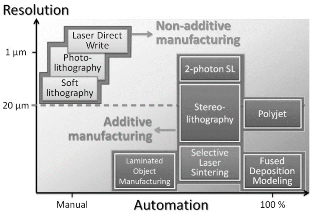
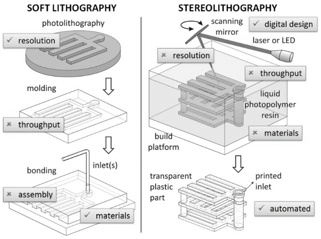
The advent of soft lithography allowed for an unprecedented expansion in the field of microfluidics. However, the vast majority of PDMS microfluidic devices are still made with extensive manual labor, are tethered to bulky control systems, and have cumbersome user interfaces, which all render commercialization difficult. On the other hand, 3D printing has begun to embrace the range of sizes and materials that appeal to the developers of microfluidic devices. Prior to fabrication, a design is digitally built as a detailed 3D CAD file. The design can be assembled in modules by remotely collaborating teams, and its mechanical and fluidic behavior can be simulated using finite-element modeling. As structures are created by adding materials without the need for etching or dissolution, processing is environmentally friendly and economically efficient. We predict that in the next few years, 3D printing will replace most PDMS and plastic molding techniques in academia.

Keywords: 3D printing; cytotoxicity; microfluidics; photochemistry; polymerization.


Figures

Figure 1.
Figure 1.
Major technical barriers for the dissemination of PDMS microfluidics to the consumer.
Figure 2.
Figure 2.
Various 3D-printing techniques. a) Selective Laser Sintering (SLS); b) Fused Deposition Modeling (FDM, also termed “thermoplastic extrusion”); c) Photopolymer Inkjet Printing; d) Binder Jetting, also trademarked as 3DP; e) Laminated Object Manufacturing (LOM); f) Stereolithography (SL). Images courtesy of CustomPartNet.com.
Figure 3.
Figure 3.
Two SL printing configurations. (a) Laser-scanning SL with the free surface configuration. (b) DLP SL with the constrained surface/”bat” configuration. Adapted from Ref. [39] with permission of IOP Publishing and David Dean.
Figure 4.
Figure 4.
Bioprinting. (a) Experimental setup for the patterned encapsulation of cells in PEG-based photocrosslinkable hydrogels by means of SL. (b) Top view of a multi-layer structure printed with the setup in (b), containing NIH 3T3 fibroblasts stained with CellTracker Green or Orange. (c) Side view of the structure in (b). (d) Confocal Z-optical section of a 3D cellular array of NIH 3T3 fibroblasts printed by SL in a gelatin-methacrylate scaffold. (e) Side view of the structure in (d). (f) Microclusters of the bacteria S. aureus printed within high-density populations of P. aeruginosa in BSA-gelatin microcontainers. (g) The survival of S. aureus confined to the microclusters in (f) is significantly enhanced. Panels (a) to (c) are reproduced from Ref. [49b] with permission of The Royal Society of Chemistry. Panels (d) and (e) are reproduced from Ref. [50b] with permission of John Wiley and Sons. Panels (f) and (g) are reproduced from Ref. [55]. Copyright 2013 National Academy of Sciences, USA.
Figure 5.
Figure 5.
Microfluidic systems printed by stereolithography (SL). (a) SL setup used to print the first microfluidic device. (b) Scanning electron micrograph (SEM) detail of the first SL-printed microfluidic device, showing a micro-connector. (c) Numerical simulations of the device in (b) at the indicated locations. (d) SEM of a micromixer printed in SU-8 by Direct Laser Writing (DLW). (e) Numerical simulation of the mixing performance of the device printed in (d); the mixing efficiency η measured at a distance 5 times the width of the channel is η = 90% for Re = 1 and a Peclet number = 1,000. (f) Digital rendering of a microfluidic “lobster trap” for bacteria; this structure was fabricated in bovine serum albumin in ~2 min from a sequence of 120 masks, each one separated by a 0.3 μm vertical step of the focal plane. (g) E. Coli colony forming at the bottom of the lobster trap. (h) Overnight incubation of the colony resulted in growth of the colony into the upper portion of the trap. Panel (a) is reproduced from Ref. [33b] with permission of the authors. Panels (b) and (c) are reproduced from Ref. [56] with permission of The Royal Society of Chemistry. Panels (d) and (e) are reproduced from Ref. [57] with permission of The Royal Society of Chemistry. Panels (f) to (h) are reproduced from Ref. [58] with permission of John Wiley and Sons.
Figure 6.
Figure 6.
Stainless steel flow device printed by selective laser sintering (SLS). Reproduced from Ref. [62] with permission of The Royal Society of Chemistry.
Figure 7.
Figure 7.
Microfluidic devices printed by PolyJet. (a) The channel is 500 μm wide and has been mechanically cleared with a cylindrical probe. (b) PolyJet test prints of two microfluidic devices; the core of the channel was defined with a sacrificial material and dissolution was attempted with NaOH; as red dye is introduced into the inlet, it demonstrates that small/very long channels cannot be cleared of the sacrificial material. (c) Schematics and (d) photograph of a nuclear magnetic resonance (NMR) bubble pump printed by PolyJet. Panel (a) is reproduced from Ref. [63] with permission of The Royal Society of Chemistry. Panel (b) is contributed by Rob Ameloot and Clement Achille. Panels (c) and (d) are reproduced from Ref. [65] with permission of The Royal Society of Chemistry.
Figure 8.
Figure 8.
Microfluidic devices produced by molding features printed with Fused Deposition Modeling (FDM). (a) Optical micrograph of a microfluidic device printed by FDM. (b) and (c) Scanning electron micrographs of the device in (a), showing that the walls are formed by Joining plastic extruded structures (b) that are prone to form pores (c). (d) 3DTouch™ 3D Printer setup. (e) Microfluidic device printed in poly-propylene by FDM with the 3DTouch™ printer. (f) Schematic of polymer extrusion. (g) Schematic of a 3D microfluidic mixer after the sacrificial polymer has been removed. (h) Optical micrograph of a complex 3D microfluidic mixer in operation. (i) FDM-printed sacrificial isomalt scaffold. (J) Embedding of the scaffold in (i) in agarose for casting; the carbohydrate quickly dissolves in the agarose hydrogel. (k) Filling of the scaffold replica with black dye. Panels (a) to (c) are produced from Ref. [66] with permission of the authors. Panels (d) to (e) are reproduced from Ref. [72] with permission of The Royal Society of Chemistry. Panels (f) to (h) are reprinted from Ref. [69] by permission from Macmillan Publishers Ltd: Nature Materials, copyright 2003. Panels (i) to (k) are reproduced from Ref. [71] with permission of The Royal Society of Chemistry.
Figure 9.
Figure 9.
Microfluidic devices built by Laminated Object Manufacturing (LOM). (a) Combinatorial mixer built by LOM using 9 Mylar laminates. (b) A 96-well ELISA test built by LOM using one PMMA layer and five polycarbonate layers. For both devices, alignment between the different layers was ensured by fitting pre-patterned holes (arrows) in each layer through two vertical pins. Panels (a) and (b) are reproduced from Refs. [79] and [80], respectively, with permission of The Royal Society of Chemistry.
Figure 10.
Figure 10.
Resolution and automation trade-off in the transition from non-additive to additive manufacturing.
Figure 11.
Figure 11.
A conceptual overview of the features of merit (√) and disadvantages (×) of soft lithography and stereolithography as traditionally perceived by researchers.
Figure 12.
Figure 12.
Implementation of drainage holes to simplify device architecture. (a) In this device the channels are fabricated with a square 635 μm x 635 μm outlet hole (indicated by arrows) so that the resin can be easily drained to the exterior. (b) The drainage holes can be sealed with adhesive tape or with epoxy. Reproduced from Ref. [87] with permission of The Royal Society of Chemistry.
Figure 13.
Figure 13.
Biocompatibility of SL prints. (a) C2C12 cells cultured on tissue culture polystyrene (TCPS) control surfaces coated with Matrigel; the cells have been stained for viability with Live/Dead cell stain after 1 day in culture. (b) C2C12 cells cultured on WaterShed surfaces coated with Matrigel using the same seeding and coating protocols as in (a); cell viability on WaterShed surfaces is indistinguishable from that on tissue culture polystyrene surfaces. (c) SEM of hollow microneedles fabricated in e-shell 200 by DLP SL. (d & e) SEM of microneedles fabricated in Ormocer by DLW. Panels (a) and (b) are reproduced from Ref. [87] with permission of The Royal Society of Chemistry. Panel (c) is reprinted from Ref. [88] with permission. Copyright 2011, AIP Publishing LLC. Panels (d) and (e) are reproduced from Ref. [89] with permission of John Wiley and Sons.
Figure 14.
Figure 14.
Multi-material SL printing. (a) SL-printed cube in a super-hydrophobic resin; note that a droplet of dye deposited on the cube does not penetrate the cube. (b) SL-printed sphere in a super-hydrophobic resin; the sphere is filled with dye, yet it does not leak through its 1 mm-side hexagonal holes (see inset). (c & d) Schematic side and top view, respectively, of a droplet generator. (e) SL print of the device in (c); the inner channel has an internal diameter of 50 μm and the fabrication accuracy is ~5 μm. (f) Droplet generation in the SL-printed device shown in (e). (g) A 3-material SL print; the chess piece has internal structures. (h) A two-material SL print; the red tips are printed in an elastomeric resin. Panel (a) and (b) are reproduced from Ref. [107] with permission of The Royal Society of Chemistry. Panels (c) to (f) are reproduced from Ref. [110] with permission of the Japan Oil Chemists’ Society. Panel (g) is reproduced from Ref. [84a] with permission of Springer Science and Business Media. Panel (h) is reproduced from Ref. [84b] with permission of the authors.
Figure 15.
Figure 15.
Modular microfluidics. (a) A modular mixer built by SL. (b) A modular droplet generator built by SL. (c) Example of user-friendly connectivity (here, an industry-standard Luer-Lock connector printed by SL). (d) Complex bioreactor printed by SL. (e & f) A complex mixer printed with a commercial desktop SL system. Panel (a) is reproduced from Ref. [117b] with permission of The Royal Society of Chemistry. Panel (b) is reproduced from Ref. [117c]. Copyright 2014 National Academy of Sciences, USA. Panel (c) is reproduced from Ref. [12] with permission of The Royal Society of Chemistry. Panel (d) is reproduced from Ref. [119] with permission of American Society for Microbiology. Panels (e) and (f) are reproduced from Ref. [120] with permission. Copyright 2014 American Chemical Society.
Figure 16.
Figure 16.
3D-printed valves, switches and pumps. (a) Photograph of a single-valve device 3D-printed in WaterShed XC 11122 resin. (b & c) Micrographs showing the dye-filled valve in its open (b) and closed (c) states. (d & e) Side-view schematics depicting a valve in its open (d) and closed (e) states. (f) Photograph of a switching device selecting for solution passing through the valve on the left. (g) A peristaltic pump during an actuation phase in which only the middle valve is open. Panels (a) through (g) are reproduced from Ref. [87] with permission of The Royal Society of Chemistry.
Figure 17.
Figure 17.
3D-printed “pumping lid”. (a) The “pumping lid” (grey) produces a positive pressure by turning down on a guiding structure that contains a soft elastomeric cup. (b & c) The lid can lock at various (“a/b/c”) positions (indicated in dotted lines or rectangles), each of which produces different pressures. (d) Experimental pressure profile obtained by turning the lid between the three positions. A similar design can generate negative pressures. (e) Schematic of a three-cup composite pumping lid for producing three different pressures in the same device. (f) Micrograph of the Junction at which three channels combine to produce a heterogeneous laminar flow. (g) Different composite lids (top row schematics) can be used to produce different flow profiles (middle row) that agree very well with the predictions of the flow profiles (bottom row) based on the pressures produced by the lids and the device geometry. Reproduced from Ref. [64] with permission of The Royal Society of Chemistry.

References

    1. Whitesides GM, Nature 2006, 442, 368. - PubMed
    1. Dittrich PS, Manz A, Nature Rev Drug Disc 2006, 5, 210; - PubMed
    2. El-Ali J, Sorger PK, Jensen KF, Nature 2006, 442, 403. - PubMed
    1. Sackmann EK, Fulton AL, Beebe DJ, Nature 2014, 507, 181. - PubMed
    1. Xia YN, Whitesides GM, Angew. Chem.-Int. Edit. Engl 1998, 37, 551.
    1. Unger MA, Chou HP, Thorsen T, Scherer A, Quake SR, Science 2000, 288, 113; - PubMed
    2. Hosokawa K, Maeda R, J. Micromech. Microeng 2000, 10, 415;
    3. Thorsen T, Maerkl SJ, Quake SR, Science 2002, 298, 580. - PubMed