

Lab-on-a-chip workshop activities for secondary school students
- PMID: 26865902
- PMCID: PMC4744233
- DOI: 10.1063/1.4940884
Lab-on-a-chip workshop activities for secondary school students
Abstract
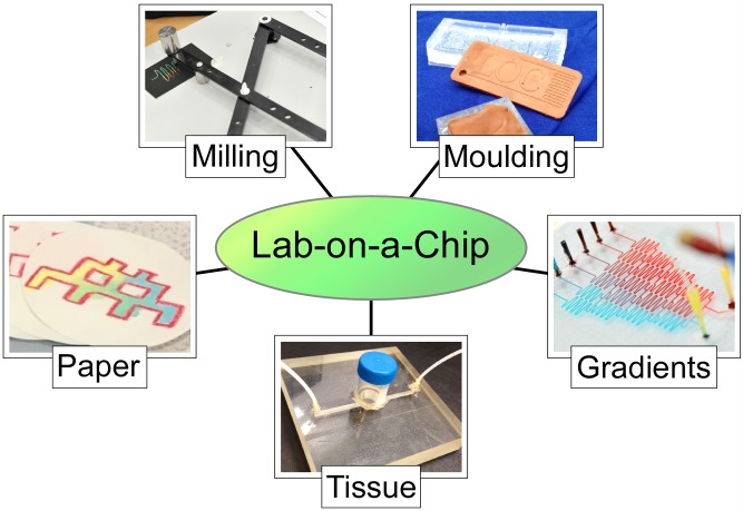
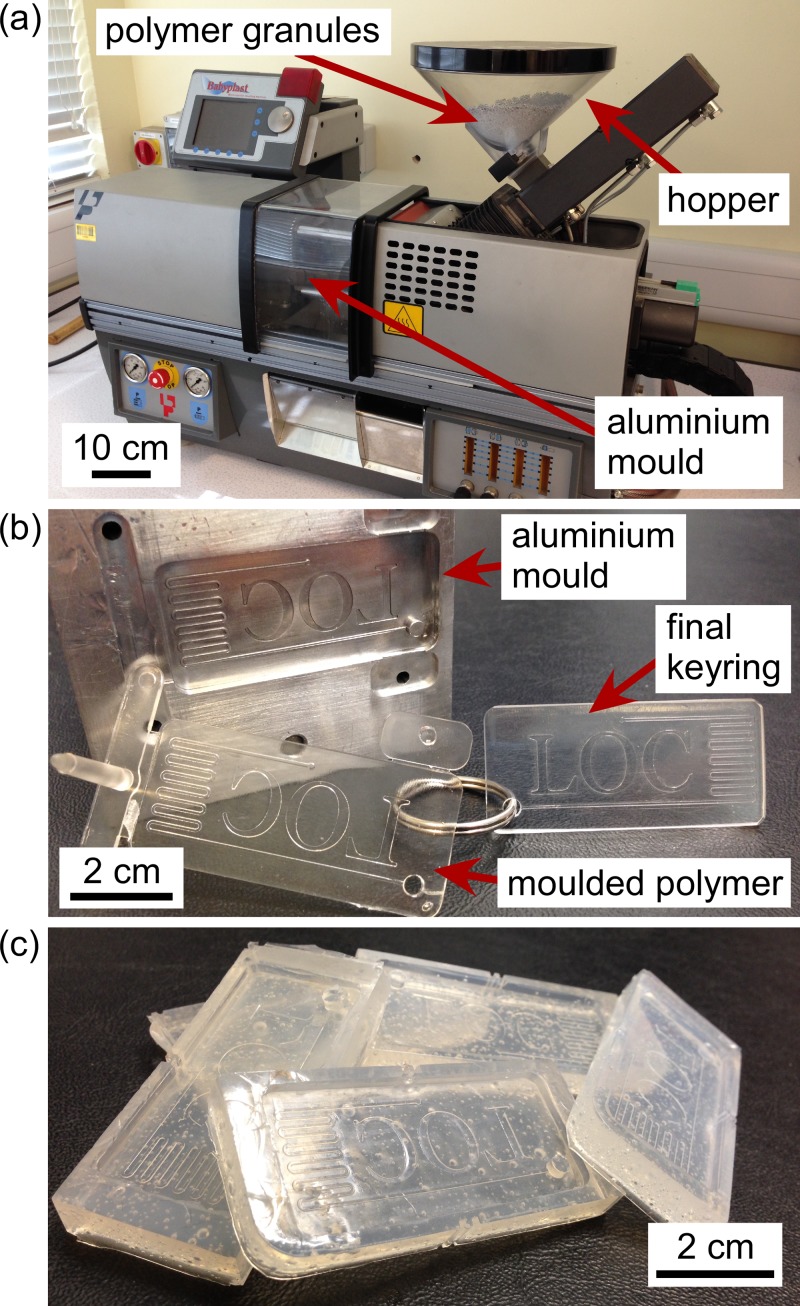
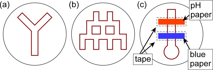
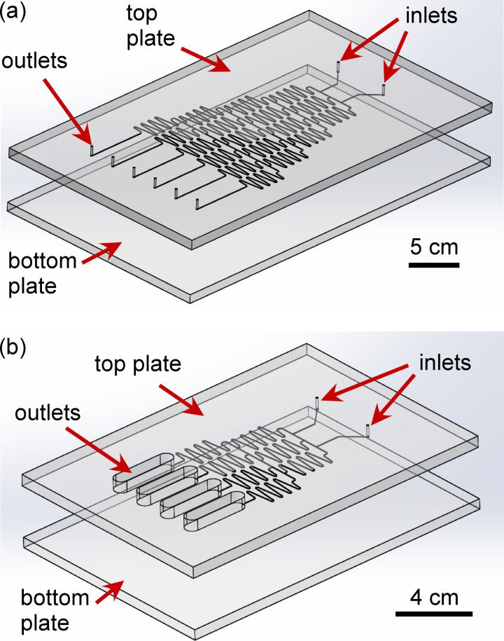
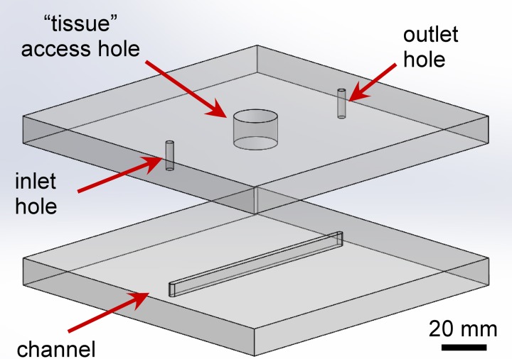
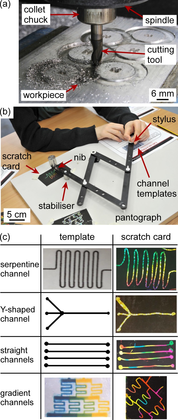
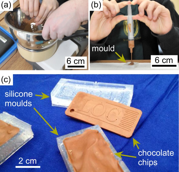
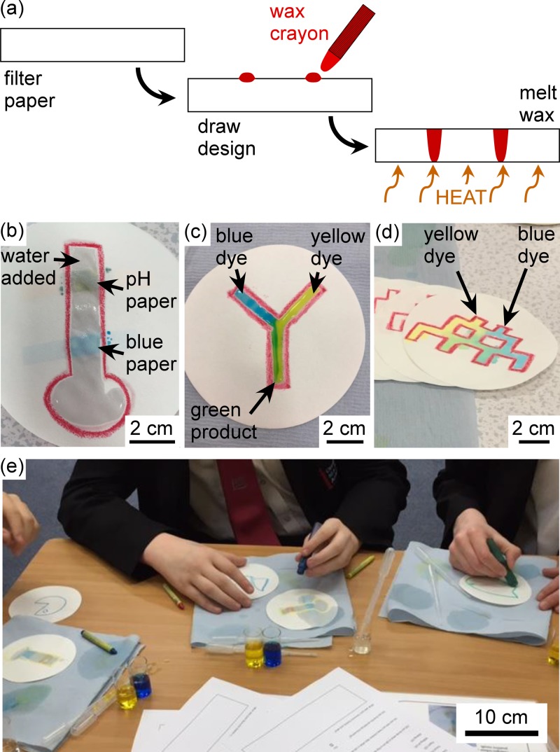
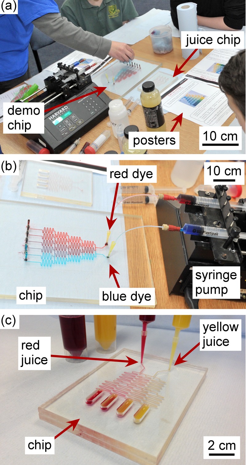
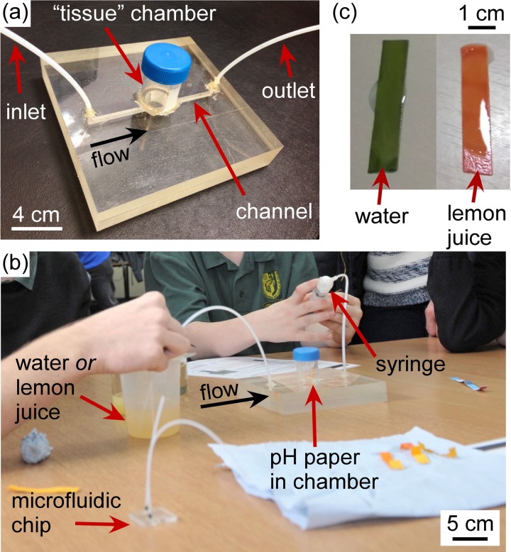
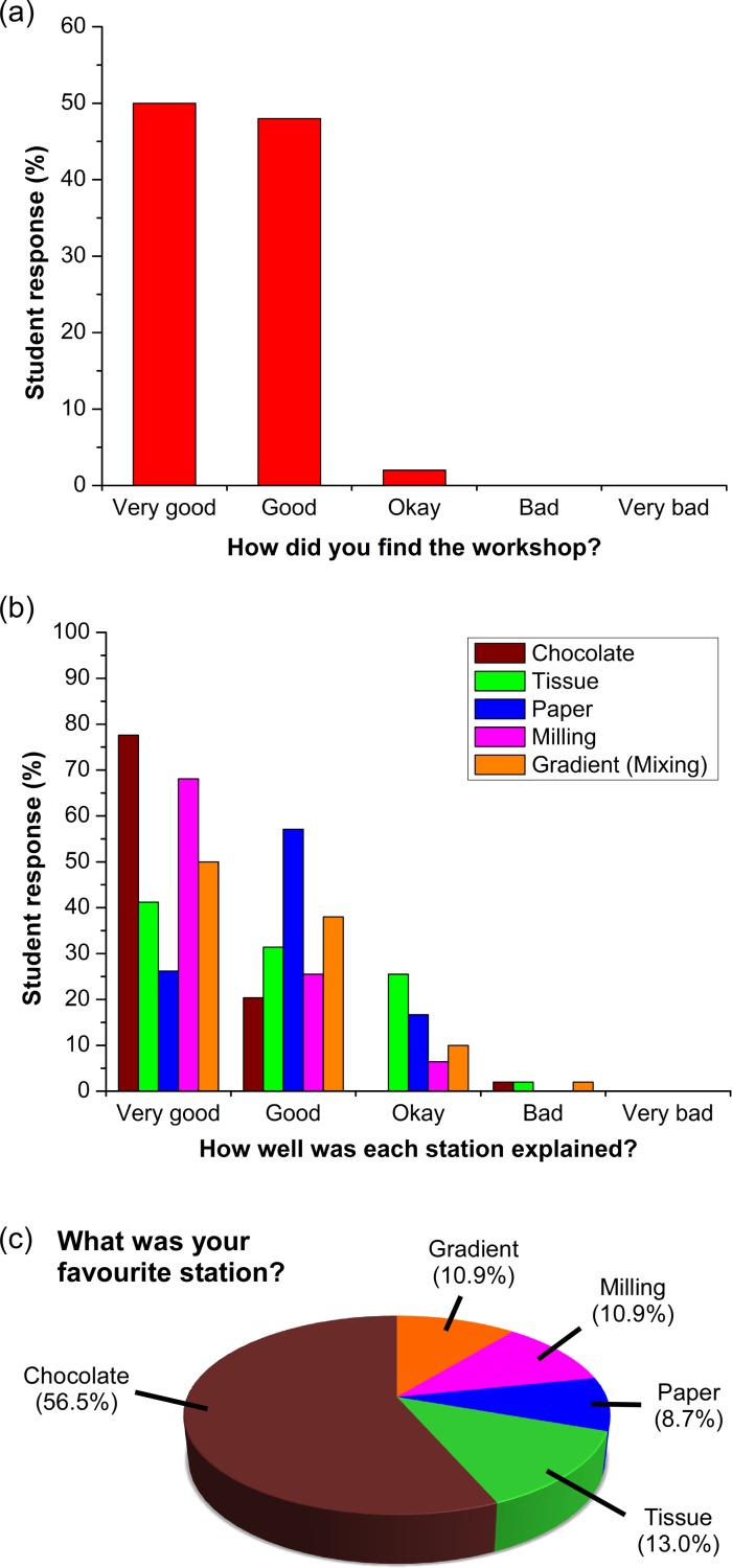
The ability to engage and inspire younger generations in novel areas of science is important for bringing new researchers into a burgeoning field, such as lab-on-a-chip. We recently held a lab-on-a-chip workshop for secondary school students, for which we developed a number of hands-on activities that explained various aspects of microfluidic technology, including fabrication (milling and moulding of microfluidic devices, and wax printing of microfluidic paper-based analytical devices, so-called μPADs), flow regimes (gradient formation via diffusive mixing), and applications (tissue analysis and μPADs). Questionnaires completed by the students indicated that they found the workshop both interesting and informative, with all activities proving successful, while providing feedback that could be incorporated into later iterations of the event.
Figures
Similar articles
-
Single step and mask-free 3D wax printing of microfluidic paper-based analytical devices for glucose and nitrite assays.Talanta. 2019 Mar 1;194:837-845. doi: 10.1016/j.talanta.2018.10.104. Epub 2018 Nov 2. Talanta. 2019. PMID: 30609613
-
Advances in Paper-Based Analytical Devices.Annu Rev Anal Chem (Palo Alto Calif). 2020 Jun 12;13(1):85-109. doi: 10.1146/annurev-anchem-061318-114845. Epub 2020 Jan 27. Annu Rev Anal Chem (Palo Alto Calif). 2020. PMID: 31986055 Review.
-
Capillary-driven microfluidic paper-based analytical devices for lab on a chip screening of explosive residues in soil.J Chromatogr A. 2016 Mar 4;1436:28-33. doi: 10.1016/j.chroma.2016.01.054. Epub 2016 Jan 24. J Chromatogr A. 2016. PMID: 26850317
-
Characteristics of Microfluidic Paper-based Analytical Devices Fabricated by Four Different Methods.Anal Sci. 2018;34(1):39-44. doi: 10.2116/analsci.34.39. Anal Sci. 2018. PMID: 29321455
-
Technical aspects and challenges of colorimetric detection with microfluidic paper-based analytical devices (μPADs) - A review.Anal Chim Acta. 2017 Jun 1;970:1-22. doi: 10.1016/j.aca.2017.03.037. Epub 2017 Mar 27. Anal Chim Acta. 2017. PMID: 28433054 Review.
Cited by
-
Student-led microfluidics lab practicals: Improving engagement and learning outcomes.Biomicrofluidics. 2016 Jun 8;10(3):034117. doi: 10.1063/1.4953448. eCollection 2016 May. Biomicrofluidics. 2016. PMID: 27375822 Free PMC article.
-
"Learning on a chip:" Microfluidics for formal and informal science education.Biomicrofluidics. 2019 Jul 9;13(4):041501. doi: 10.1063/1.5096030. eCollection 2019 Jul. Biomicrofluidics. 2019. PMID: 31431815 Free PMC article. Review.
-
Multiplexed Paper Microfluidics for Titration and Detection of Ingredients in Beverages.Sensors (Basel). 2019 Mar 14;19(6):1286. doi: 10.3390/s19061286. Sensors (Basel). 2019. PMID: 30875737 Free PMC article.
-
Demonstrating the Use of Optical Fibres in Biomedical Sensing: A Collaborative Approach for Engagement and Education.Sensors (Basel). 2020 Jan 10;20(2):402. doi: 10.3390/s20020402. Sensors (Basel). 2020. PMID: 31936827 Free PMC article.
-
Lab-on-a-Chip: Frontier Science in the Classroom.J Chem Educ. 2018 Feb 13;95(2):267-275. doi: 10.1021/acs.jchemed.7b00506. Epub 2017 Dec 15. J Chem Educ. 2018. PMID: 30258250 Free PMC article.
References
-
- Tarn M. D. and Pamme N., “ Microfluidics,” in Elsevier Reference Module in Chemistry, Molecular Sciences and Chemical Engineering, edited by Reedijk J. ( Elsevier, Waltham, MA, 2013).
LinkOut - more resources
Full Text Sources
Other Literature Sources
Miscellaneous