. 2016 May;93(5):521-33.
doi: 10.1097/OPX.0000000000000820.

High-Power Prismatic Devices for Oblique Peripheral Prisms

Affiliations

High-Power Prismatic Devices for Oblique Peripheral Prisms

Eli Peli et al. Optom Vis Sci. 2016 May.

Abstract

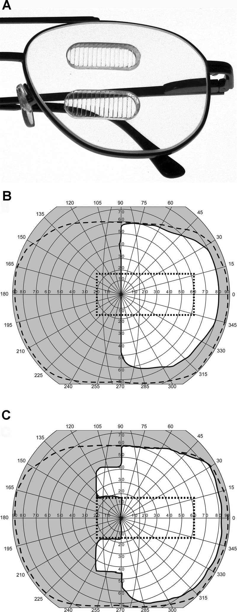
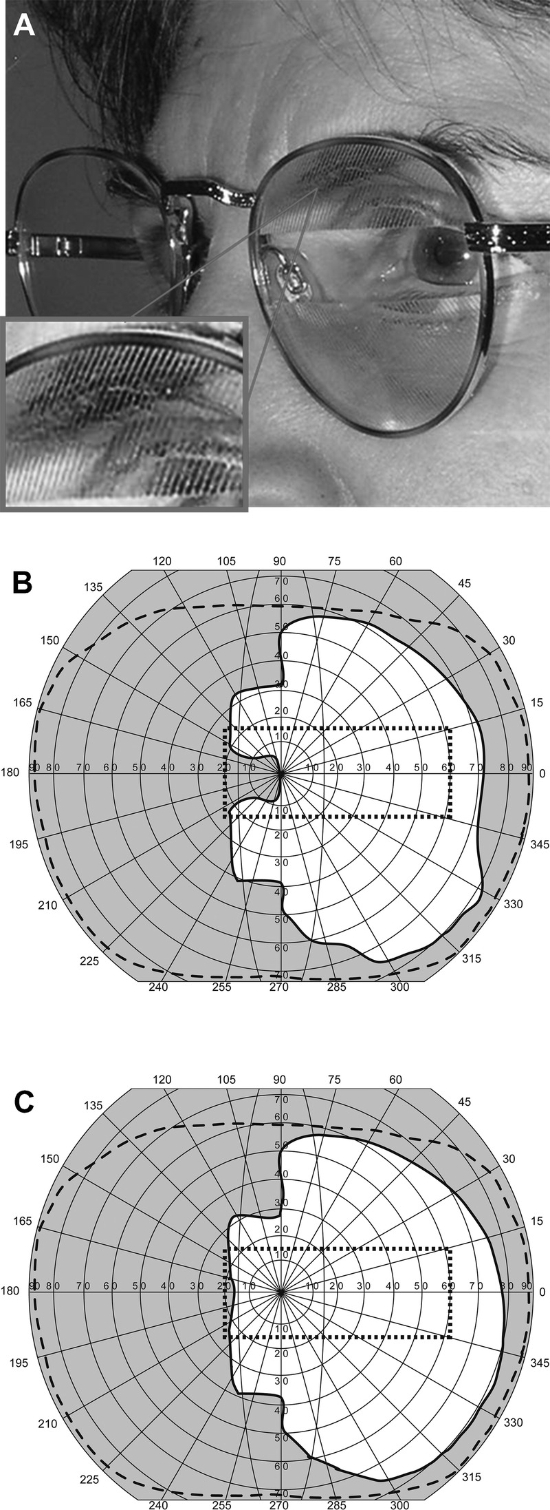
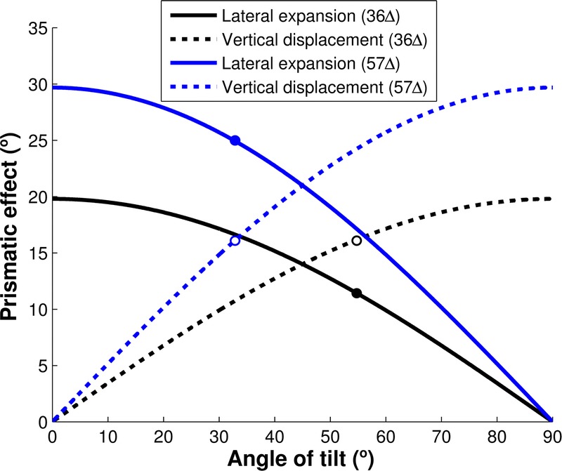
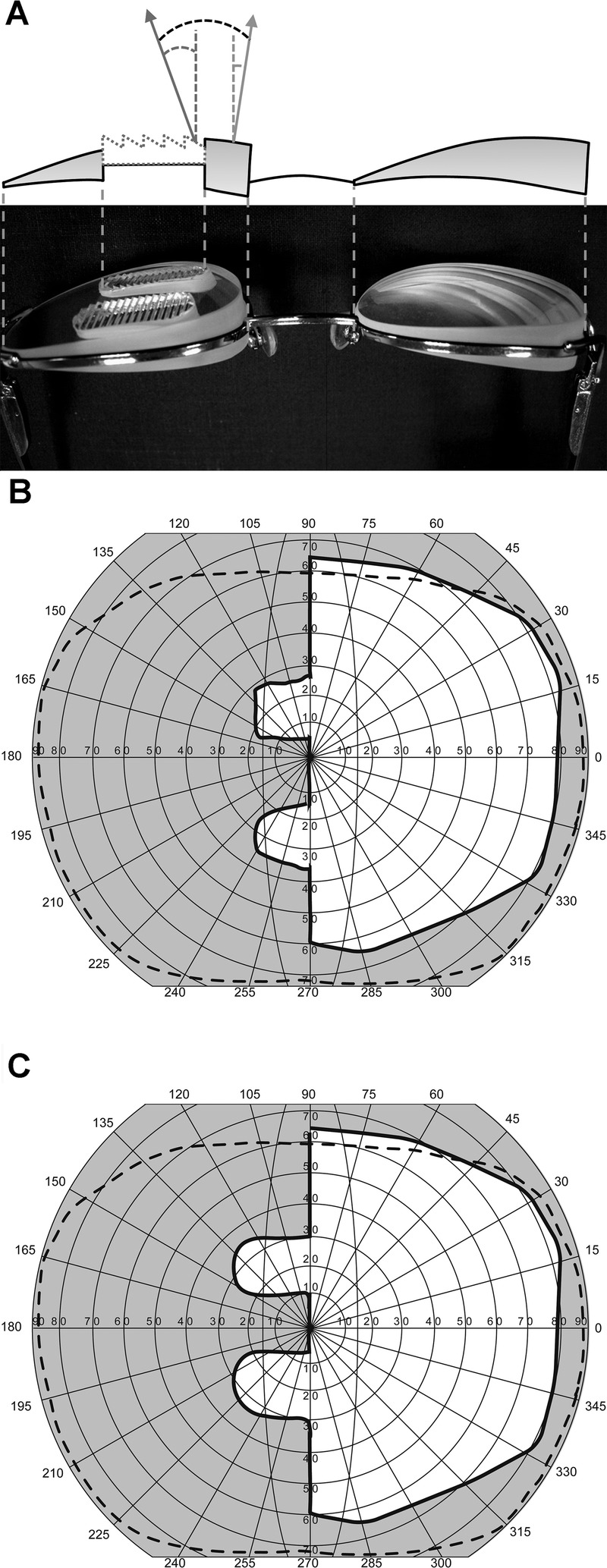
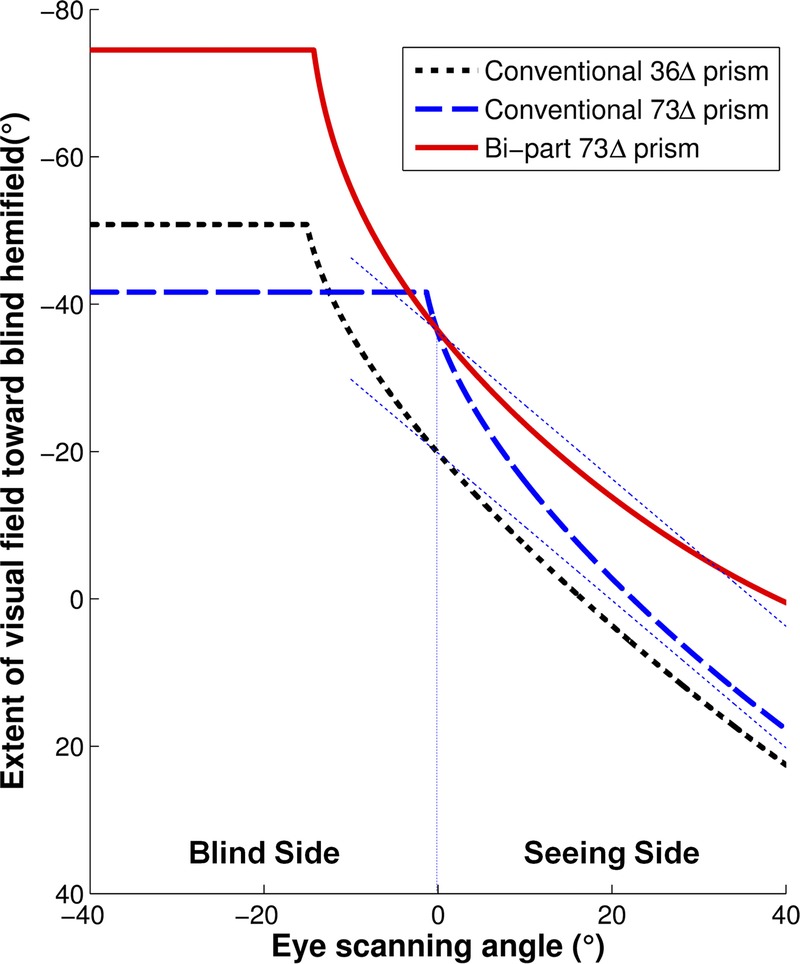
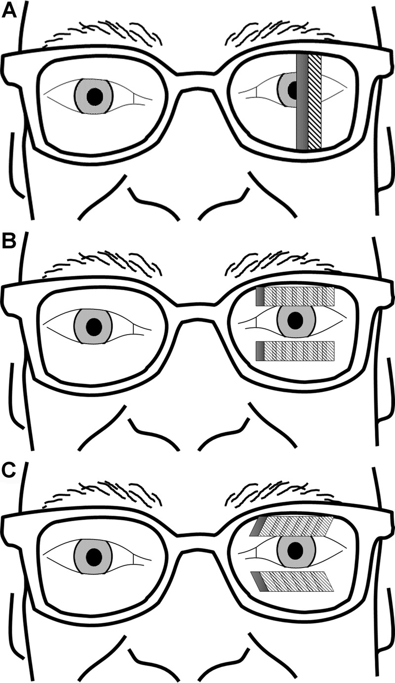
Purpose: Horizontal peripheral prisms for hemianopia provide field expansion above and below the horizontal meridian; however, there is a vertical gap leaving the central area (important for driving) without expansion. In the oblique design, tilting the bases of both prism segments toward the horizontal meridian moves the field expansion area vertically and centrally (closing the central gap) while the prisms remain in the peripheral location. However, tilting the prisms results also in a reduction of the lateral field expansion. Higher prism powers are needed to counter this effect.

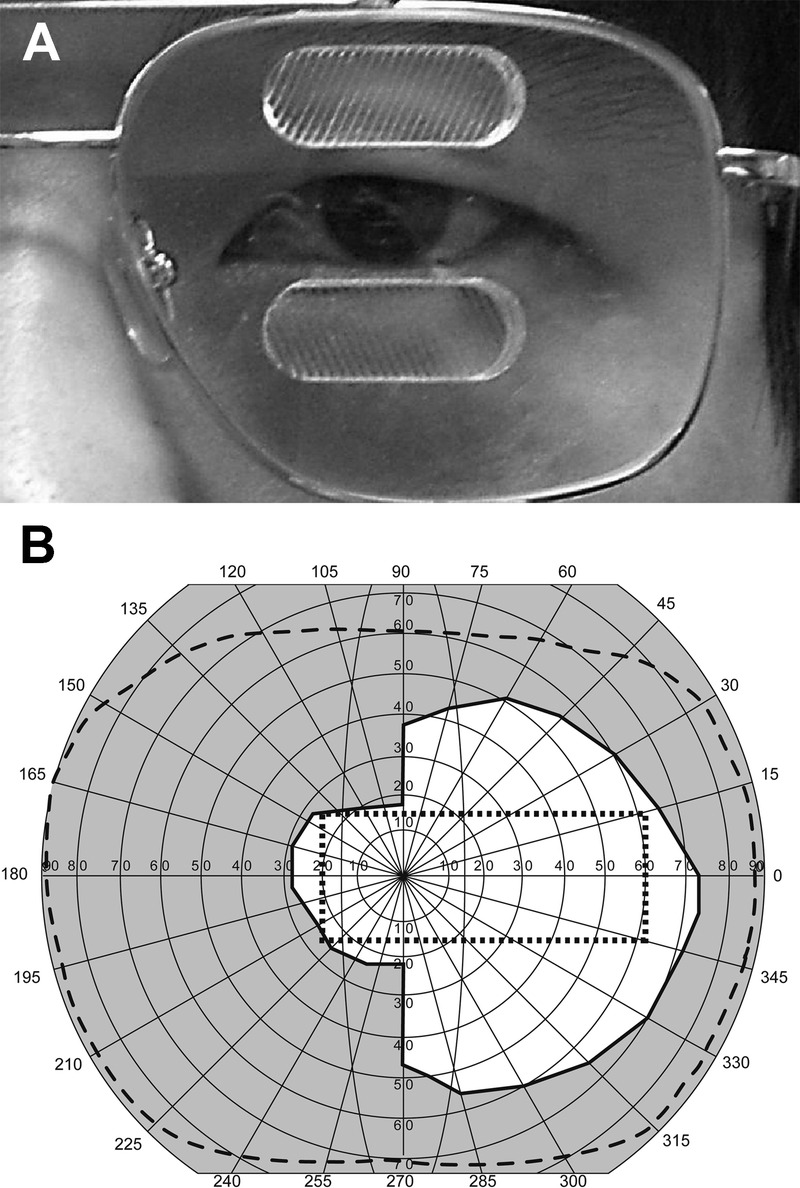
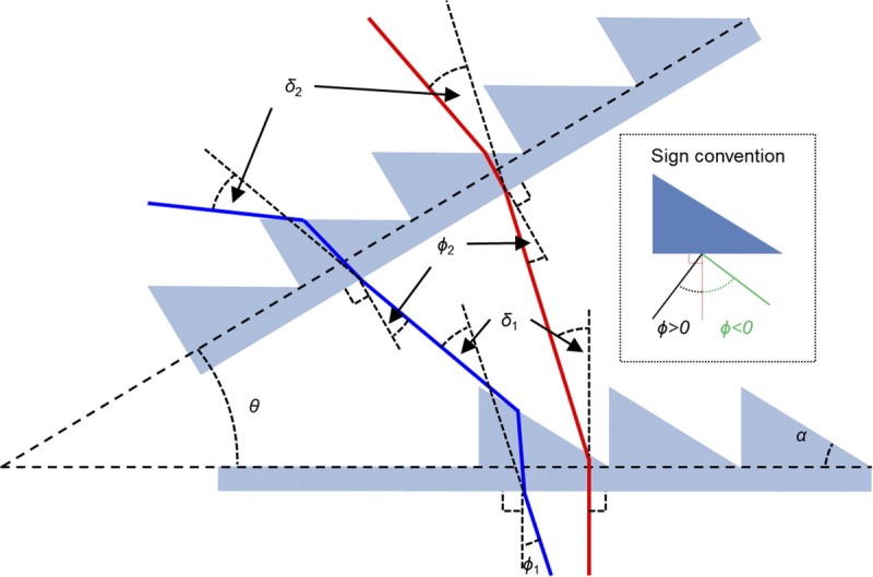
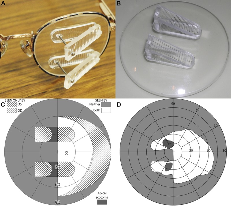
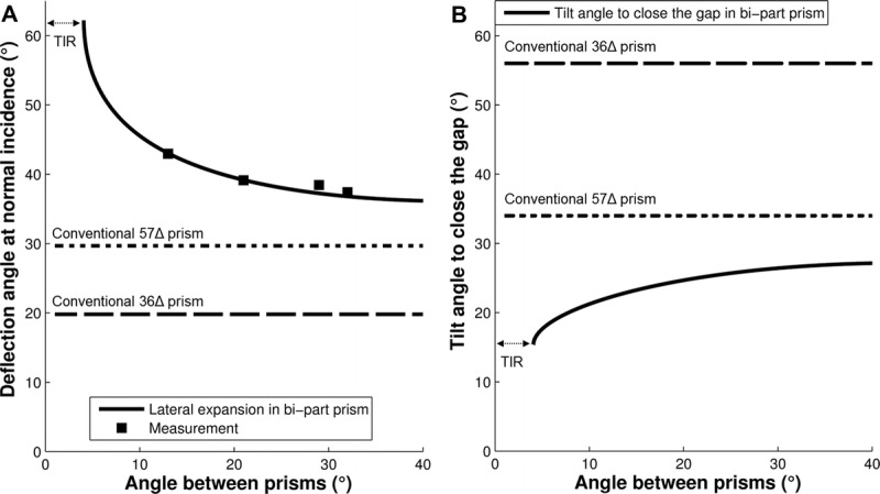
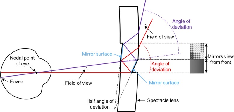
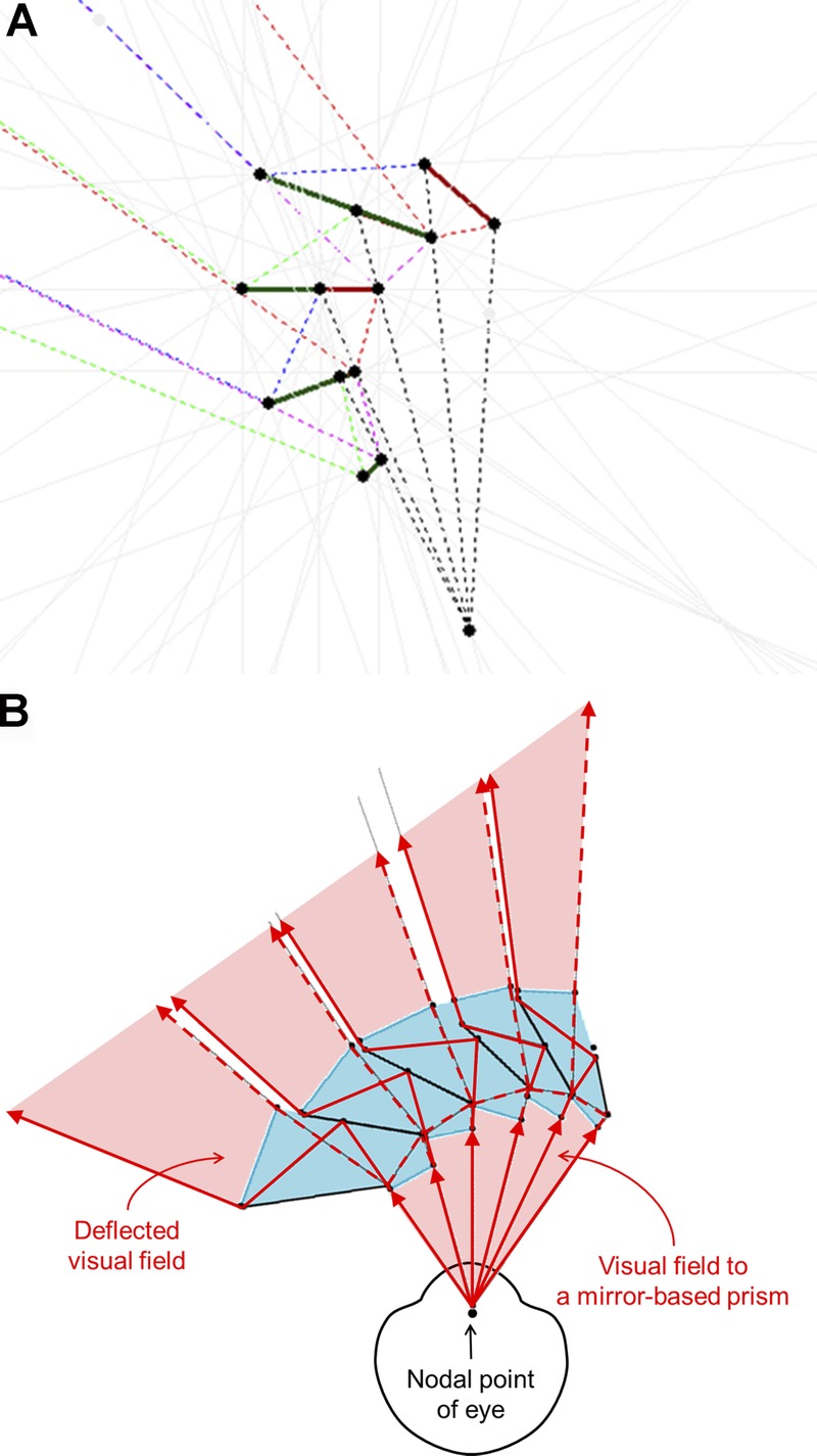
Methods: We developed, implemented, and tested a series of designs aimed at increasing the prism power to reduce the central gap while maintaining wide lateral expansion. The designs included inserting the peripheral prisms into carrier lenses that included yoked prism in the opposite direction, combination of two Fresnel segments attached at the base and angled to each other (bi-part prisms), and creating Fresnel prism-like segments from nonparallel periscopic mirror pairs (reflective prisms).

Results: A modest increase in lateral power was achieved with yoked-prism carriers. Bi-part combination of 36Δ Fresnel segments provided high power with some reduction in image quality. Fresnel reflective prism segments have potential for high power with superior optical quality but may be limited in field extent or by interruptions of the expanded field. Extended apical scotomas, even with unilateral fitting, may limit the utility of very high power prisms. The high-power bi-part and reflective prisms enable a wider effective eye scanning range (more than 15 degrees) into the blind hemifield.

Conclusions: Conventional prisms of powers higher than the available 57Δ are limited by the binocular impact of a wider apical scotoma and a reduced effective eye scanning range to the blind side. The various designs that we developed may overcome these limitations and find use in various other field expansion applications.


Figures

FIGURE 1
FIGURE 1
(A) Permanent peripheral prism glasses in the horizontal design constructed with embedded rigid PMMA Fresnel prism inserts of 36Δ above and below the pupil base-left on the left lens only for a patient with left hemianopia. (B) Binocular visual field of a patient with left hemianopia. (C) Binocular visual field of the same patient wearing horizontal peripheral prisms resulting in a field expansion of about 20 degrees. The outer dashed line represents the normal binocular visual field and the dotted rectangle represents the field of view through the windshield of a typical car.
FIGURE 2
FIGURE 2
(A) Peripheral prism glasses in the oblique design constructed with press-on Fresnel prisms of 40Δ (see magnified inset) above and below the pupil mounted on the back of the left lens only for a patient with left hemianopia. The upper segment is oriented with the base out and down and the lower segment with the base out and up. (B) Binocular visual field of a patient with left hemianopia with oblique press-on Fresnel 40Δ prisms with the apex-base axes at 30 degrees tilt and with 11-mm interprism separation. The vertical gap between the expansion areas is reduced compared with the horizontal design (Fig. 1C), but the lateral field expansion effect is a little smaller. Note that the field in Fig. 1C was measured with 36Δ prisms. (C) Binocular visual field of the same patient with the same prisms but with a separation of 9 mm, which further reduces the gap. The dotted rectangle indicates the field of view through the windshield of a typical car.
FIGURE 3
FIGURE 3
The trade-off relationship between oblique tilt angle and the lateral expansion and vertical displacement. Increasing the tilt angle of the base-apex axis increases the vertical shift (dashed curves) but reduces the lateral expansion (solid curves) for 36Δ (black curves) and 57Δ (blue curves) PMMA prisms. For small angles of tilt, the gain in vertical shift (gap reduction) is higher in magnitude than the loss in lateral expansion. To close the standard 12-mm interprism separation (equivalent to 33 degrees vertical gap between the prism expansion areas or 16.5 degrees for each prism segment), the 36Δ prisms require 56 degrees tilt angle (black open marker), which reduces the lateral expansion to only 11 degrees (black filled marker). However, the 57Δ oblique prisms can close the gap with just 34 degrees tilt (blue open marker) and still provide 25 degrees lateral expansion (blue filled marker).
FIGURE 4
FIGURE 4
(A) Commercially available rigid PMMA oblique peripheral prism of 57Δ embedded in the left lens for a patient with left hemianopia. (B) Binocular visual field of a patient with left hemianopia wearing oblique prisms of 57Δ (30 degrees tilt angle) with a 12-mm interprism separation. Lateral 26 degrees field expansion and vertical 15 degrees shift were achieved with each segment; the gap between the prism expansion areas was eliminated. Note that the far peripheral field of this patient is smaller than a normal visual field (dashed line), yet the field expansion achieved by the oblique prism covers the view through the car windshield.
FIGURE 5
FIGURE 5
Yoked prism carrier lenses for increasing the effective lateral prismatic power and field expansion. (A) Horizontal peripheral prism glasses (rigid PMMA 36Δ) for left hemianopia embedded in one of the yoked ophthalmic prism carriers base right (10Δ). The prismatic effects of the carrier and peripheral prism sum up. (B) The binocular field of a patient with left hemianopia wearing 36Δ peripheral prism glasses showing about 20 degrees expansion. (C) The binocular field of the same patient when wearing the glasses shown in A with an increase in expansion of about 6 degrees (10Δ). The vertical difference in the positions of the expansion areas between B and C is an artifact of different head positioning in the perimeter. The same effect of head tilt is in play in daily use of the peripheral prism glasses.
FIGURE 6
FIGURE 6
The rays’ paths through a bi-part double Fresnel prism. The two Fresnel prism segments with apical angle α are inclined relative to each other at angle &thetas;. The total deflection of light δ is the sum of the deflection powers of the two segments (δ = δ1 + δ2). As with a conventional prism, the effective prism power of the bi-part prism is increased by a negative angle of incidence and is limited by TIR (blue ray). This design offers some flexibility through a trade-off between a wider eye scanning range and a higher nominal power (see Fig. 9). When the angle of incidence increases, the effective prism power of the bi-part prism increases (from red rays to blue rays on the left). If the eye scanning angle in the first prism (closer to the eye) is just under the critical angle of incidence (blue rays), the angle of incidence in the second prism should be higher than the critical angle of incidence to prevent TIR (blue rays). This is achieved by increasing angle &thetas;.
FIGURE 7
FIGURE 7
Bi-part prisms segments. (A) Spectacle-mounted bi-part system with two prisms of 36Δ and an adjustable screw mount enabling adjustment of the angle between the two prisms. (B) Bi-part prism constructed with a fixed angle between the two prisms, which could be used in prescription production. Note here that one segment (lower) is constructed from 36Δ Fresnel prisms and the other with 57Δ prisms. (C) Calculated binocular Goldmann visual field for a patient with left hemianopia wearing the bi-part horizontal peripheral prisms shown in A with 29 degrees between the two prisms. The large apical scotomas extend into the left hemifield, creating paracentral scotomas in the binocular field. (D) Measured binocular visual field of a patient with left hemianopia wearing bi-part prism glasses. The paracentral scotomas are apparent in the binocular field. This patient has some overall reduction of sensitivity peripherally in addition to the hemianopia.
FIGURE 8
FIGURE 8
(A) The calculated (solid line) and measured (solid squares) deflection angles, at normal incidence, of a bi-part prism constructed from two PMMA Fresnel prisms of 36Δ as a function of angle, &thetas;, between them. The nominal deflection angle (normal incidence) for a bi-part prism converges to a fixed value of about 38 degrees (∼78Δ) for angles between the prisms larger than 29 degrees. As the angle between the prisms is reduced, the deflection angle increases rapidly and the transmittance also decreases rapidly toward the critical angle (angle of TIR). Rated prism powers of conventional 57Δ (dotted line) and 36Δ (dashed line) are illustrated. (B) The tilt angle for the oblique design (with 12-mm interprism separation) needed to close the gap (33 degrees) between the expansion areas as a function of the angle between the bi-part prisms. The tilt angle required to close the gap with conventional 57Δ (dotted line) and 36Δ (dashed line) are illustrated for comparison.
FIGURE 9
FIGURE 9
A comparison between bi-part and conventional prisms of the calculated extent of visual field as a function of eye scanning angle. For a patient with hemianopia, the extent of visual field is from primary gaze (eye scanning angle = 0 degrees; head direction) toward the blind side or prism base. At the foveal line of sight, the angle of incidence is equal to the eye scanning angle. The effective eye scanning range is limited by the angle of incidence, resulting in 50% transmittance. Within this range, the effective prism power increases as the patient scans farther toward the blind side. As a result, the increase in the extent of the visual field is larger than the scanning angle, representing prism minification (image compression). The increase in the extent of the visual field saturates when the eye scanning angle exceeds the critical angle. On eye scanning into the seeing side, the extent of field toward the blind hemifield is largely unchanged with the bi-part prism even when compared with the conventional 36Δ prism, and it is much more stable than with the conventional high-power prism. Compare with the thin dashed lines that represent a constant field extent at all scanning angles.
FIGURE 10
FIGURE 10
Spitzberg’s mirror-based periscopic design viewed from above. Together, the two mirrors form a ray-shifting device that is similar to a prism in terms of the image shift. In this illustration, the thickness of the spectacle lens is 5 mm and the angular difference of the slanted mirror surfaces is 17 degrees, giving a prism power of about 67Δ, but the field of view is limited to only about 5 degrees.
FIGURE 11
FIGURE 11
Various configurations of the mirror prism-like elements used as a field expansion device for homonymous hemianopia. (A) Spitzberg’s mirror prismatic device was designed as a single element unilateral sector prism field expander that extends vertically across the whole lens. While the prismatic deflection angle can be large, the field of view seen through this “prism” is narrow and constrained by the thickness of the carrier spectacle lens. (B) The field of view can be expanded by creating a Fresnel-like structure with segments of these elements placed one next to the other. Short elements of this type can then be used to implement the peripheral prism design. (C) Tilting the same series of mirror elements can be used to implement the oblique peripheral prism design with a higher deflection power.
FIGURE 12
FIGURE 12
Ray tracing of the field of view constraints of a reflective Fresnel prism design. (A) The mirrors-in-air design is restricted in extent by the limitations imposed by the field of view of each segment (because of lens thickness) and the increased angular rotation of the second prism in every pair, which leads to diminishing size. Shown here for approximately 40 degrees of deflection. The solid lines are mirror segments, and dashed lines are traced rays. (B) A solid design in PMMA provides additional flexibility of design, but with additional complexity. It can result in a larger extent of the Fresnel prism section than the in-air design (A). In the implementation shown here, there are very small blind areas (shown here as white gaps) that, because of their parallel tunnel-field nature, result in rapidly diminishing and negligible effects at the distances of objects of interest.
FIGURE 13
FIGURE 13
A reflective prism device demonstration unit built with double-sided mirror segments mounted on a dark surface. (A) A photo from the side showing the real target (wooden ruler) marked by a white ellipse. The user’s direction of view is shown by the thin white arrow drawn on the dark surface from left to right. (B) An image of the target is seen in the reflective prismatic device in the direction of the thick white arrow; it is shifted by 36 degrees (∼73Δ).

References

    1. Peli E. Field expansion for homonymous hemianopia by optically-induced peripheral exotropia. Optom Vis Sci 2000; 77: 453– 64. - PubMed
    1. Vargas-Martin F, Garcia-Perez MA. Visual fields at the wheel. Optom Vis Sci 2005; 82: 675– 81. - PubMed
    1. Apfelbaum HL, Ross NC, Bowers AR, Peli E. Considering apical scotomas, confusion, and diplopia when prescribing prisms for homonymous hemianopia. Transl Vis Sci Technol 2013; 2: 2. - PMC - PubMed
    1. Cohen JM, Waiss B. Visual field remediation. In: Cole RG, Rosenthal BP, eds. Remediation and Management of Low Vision. St. Louis, MO: Mosby; 1996; 1– 25.
    1. Giorgi RG, Woods RL, Peli E. Clinical and laboratory evaluation of peripheral prism glasses for hemianopia. Optom Vis Sci 2009; 86: 492– 502. - PMC - PubMed