

A new scheme for real-time high-contrast imaging in lung cancer radiotherapy: a proof-of-concept study
- PMID: 26943271
- PMCID: PMC5590640
- DOI: 10.1088/0031-9155/61/6/2372
A new scheme for real-time high-contrast imaging in lung cancer radiotherapy: a proof-of-concept study
Abstract
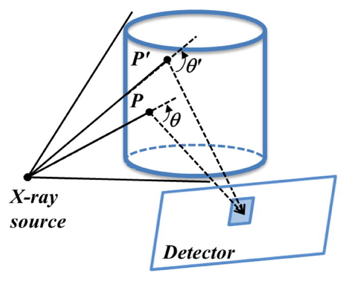
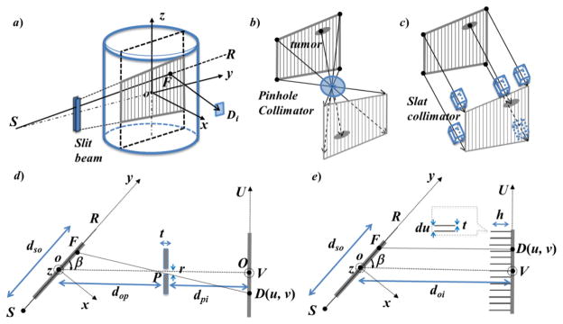
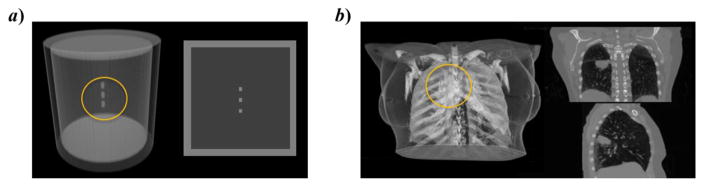
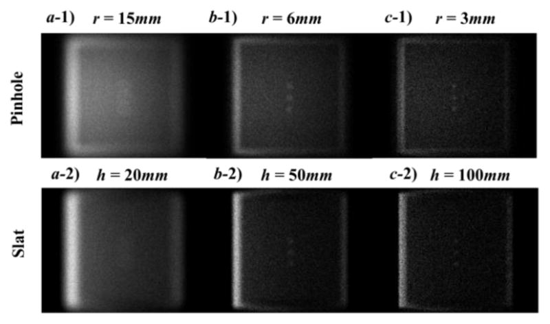
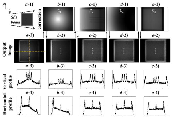
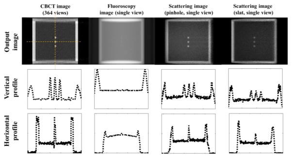
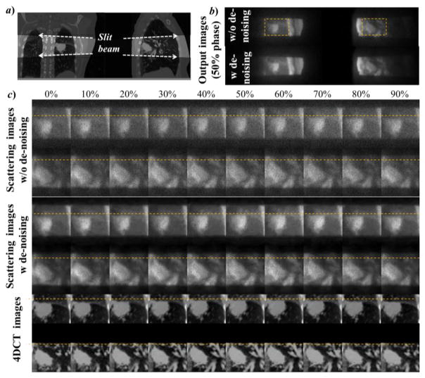
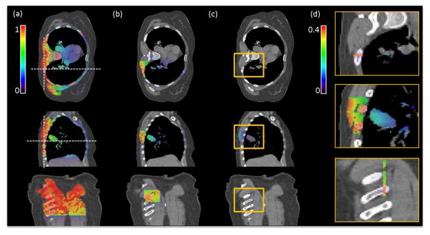
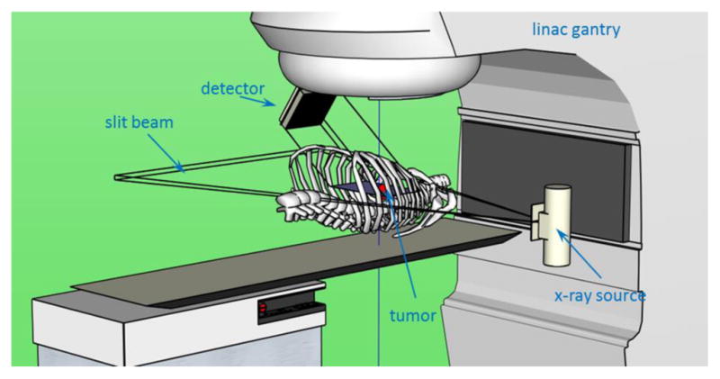
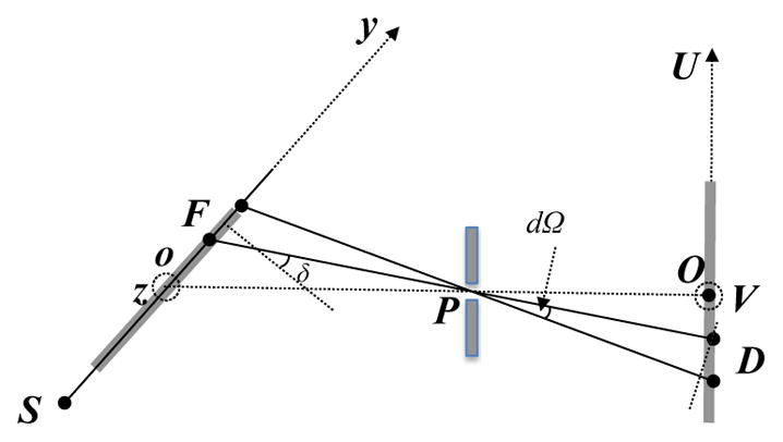
Visualization of anatomy in real time is of critical importance for motion management in lung cancer radiotherapy. To achieve real-time, and high-contrast in-treatment imaging, we propose a novel scheme based on the measurement of Compton scatter photons. In our method, a slit x-ray beam along the superior-inferior direction is directed to the patient, (intersecting the lung region at a 2D plane) containing most of the tumor motion trajectory. X-ray photons are scattered off this plane primarily due to the Compton interaction. An imager with a pinhole or a slat collimator is placed at one side of the plane to capture the scattered photons. The resulting image, after correcting for incoming fluence inhomogeneity, x-ray attenuation, scatter angle variation, and outgoing beam geometry, represents the linear attenuation coefficient of Compton scattering. This allows the visualization of the anatomy on this plane. We performed Monte Carlo simulation studies both on a phantom and a patient for proof-of-principle purposes. In the phantom case, a small tumor-like structure could be clearly visualized. The contrast-resolution calculated using tumor/lung as foreground/background for kV fluoroscopy, cone beam computed tomography (CBCT), and scattering image were 0.037, 0.70, and 0.54, respectively. In the patient case, tumor motion could be clearly observed in the scatter images. Imaging dose to the voxels directly exposed by the slit beam was ~0.4 times of that under a single CBCT projection. These studies demonstrated the potential feasibility of the proposed imaging scheme to capture the instantaneous anatomy of a patient on a 2D plane with a high image contrast. Clear visualization of the tumor motion may facilitate marker-less tumor tracking.
Figures
References
-
- Ahn S, Yi B, Suh Y, Kim J, Lee S, Shin S, Choi E. A feasibility study on the prediction of tumour location in the lung from skin motion. British journal of radiology. 2004;77:588–96. - PubMed
-
- Arslan S, Yilmaz A, Bayramgürler B, Uzman O, Nver E, Akkaya E. CT-guided transthoracic fine needle aspiration of pulmonary lesions: accuracy and complications in 294 patients. Medical science monitor: international medical journal of experimental and clinical research. 2002;8:CR493. - PubMed
-
- Berbeco R, Mostafavi H, Sharp GC, Jiang SB. Tumor tracking in the absence of radiopaque markers. The 14th International Conference on the Use of Computers in Radiation Therapy; Seoul, Korea: Jeong Publishing; 2004. pp. 433–36.
-
- Berbeco RI, Mostafavi H, Sharp GC, Jiang SB. Towards fluoroscopic respiratory gating for lung tumours without radiopaque markers. Phys Med Biol. 2005;50:4481. - PubMed
Publication types
MeSH terms
Grants and funding
LinkOut - more resources
Full Text Sources
Other Literature Sources
Medical