. 2016 Mar 22;113(12):3179-84.
doi: 10.1073/pnas.1521342113. Epub 2016 Mar 7.

Three-dimensional bioprinting of thick vascularized tissues

Affiliations

Three-dimensional bioprinting of thick vascularized tissues

David B Kolesky et al. Proc Natl Acad Sci U S A. .

Abstract

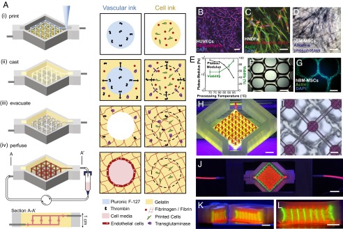
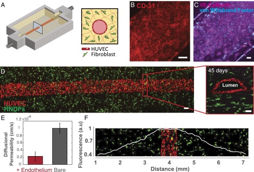
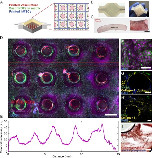
The advancement of tissue and, ultimately, organ engineering requires the ability to pattern human tissues composed of cells, extracellular matrix, and vasculature with controlled microenvironments that can be sustained over prolonged time periods. To date, bioprinting methods have yielded thin tissues that only survive for short durations. To improve their physiological relevance, we report a method for bioprinting 3D cell-laden, vascularized tissues that exceed 1 cm in thickness and can be perfused on chip for long time periods (>6 wk). Specifically, we integrate parenchyma, stroma, and endothelium into a single thick tissue by coprinting multiple inks composed of human mesenchymal stem cells (hMSCs) and human neonatal dermal fibroblasts (hNDFs) within a customized extracellular matrix alongside embedded vasculature, which is subsequently lined with human umbilical vein endothelial cells (HUVECs). These thick vascularized tissues are actively perfused with growth factors to differentiate hMSCs toward an osteogenic lineage in situ. This longitudinal study of emergent biological phenomena in complex microenvironments represents a foundational step in human tissue generation.

Keywords: biomaterials; bioprinting; stem cells; tissues; vasculature.


Conflict of interest statement

The authors declare no conflict of interest.

Figures

Fig. 1.
Fig. 1.
Three-dimensional vascularized tissue fabrication. (A) Schematic illustration of the tissue manufacturing process. (i) Fugitive (vascular) ink, which contains pluronic and thrombin, and cell-laden inks, which contain gelatin, fibrinogen, and cells, are printed within a 3D perfusion chip. (ii) ECM material, which contains gelatin, fibrinogen, cells, thrombin, and TG, is then cast over the printed inks. After casting, thrombin induces fibrinogen cleavage and rapid polymerization into fibrin in both the cast matrix, and through diffusion, in the printed cell ink. Similarly, TG diffuses from the molten casting matrix and slowly cross-links the gelatin and fibrin. (iii) Upon cooling, the fugitive ink liquefies and is evacuated, leaving behind a pervasive vascular network, which is (iv) endothelialized and perfused via an external pump. (B) HUVECs growing on top of the matrix in 2D, (C) HNDFs growing inside the matrix in 3D, and (D) hMSCs growing on top of the matrix in 2D. (Scale bar: 50 µm.) (E and F) Images of printed hMSC-laden ink prepared using gelatin preprocessed at 95 °C before ink formation (E) as printed and (F) after 3 d in the 3D printed filament where actin (green) and nuclei (blue) are stained. (G) Gelatin preprocessing temperature affects the plateau modulus and cell viability after printing. Higher temperatures lead to lower modulus and higher HNDF viability postprinting. (H) Photographs of interpenetrated sacrificial (red) and cell inks (green) as printed on chip. (Scale bar: 2 mm.) (I) Top-down bright-field image of sacrificial and cell inks. (Scale bar: 50 µm.). (J–L) Photograph of a printed tissue construct housed within a perfusion chamber (J) and corresponding cross-sections (K and L). (Scale bars: 5 mm.)
Fig. 2.
Fig. 2.
Three-dimensional vascularized tissues remain stable during long-term perfusion. (A) Schematic depicting a single HUVEC-lined vascular channel supporting a fibroblast cell-laden matrix and housed within a 3D perfusion chip. (B and C) Confocal microscopy image of the vascular network after 42 d, CD-31 (red), vWF (blue), and VE-Cadherin (magenta). (Scale bars: 100 µm.) (D) Long-term perfusion of HUVEC-lined (red) vascular network supporting HNDF-laden (green) matrix shown by top-down (Left) and cross-sectional confocal microscopy at 45 d (Right). (Scale bar: 100 µm.) (E) Quantification of barrier properties imparted by endothelial lining of channels, demonstrated by reduced diffusional permeability of FITC-dextran. (F) GFP-HNDF distribution within the 3D matrix shown by fluorescent intensity as a function of distance from vasculature.
Fig. 3.
Fig. 3.
Osteogenic differentiation of thick vascularized tissue. (A) Schematic depicting the geometry of the printed heterogeneous tissue within the customized perfusion chip, wherein the branched vascular architecture pervades hMSCs that are printed into a 3D lattice architecture, and HNDFs are cast within an ECM that fills the interstitial space. (B) Photographs of a printed tissue construct within and removed from the customized perfusion chip. (C) Comparative cross-sections of avascular tissue (Left) and vascularized tissue (Right) after 30 d of osteogenic media perfusion with alizarin red stain showing location of calcium phosphate. (Scale bar: 5 mm.) (D) Confocal microscopy image through a cross-section of 1-cm-thick vascularized osteogenic tissue construct after 30 d of active perfusion and in situ differentiation. (Scale bar: 1.5 mm.) (E) Osteocalcin intensity across the thick tissue sample inside the red lines shown in C. (F) High-resolution image showing osteocalcin (purple) localized within hMSCs, and they appear to take on symmetric osteoblast-like morphologies. (Scale bar: 100 µm.) After 30 d (G and H), thick tissue constructs are stained for collagen-I (yellow), which appears to be localized near hMSCs. (Scale bars: 200 µm.) (I) Alizarin red is used to stain calcium phosphate deposition, and fast blue is used to stain AP, indicating tissue maturation and differentiation over time. (Scale bar: 200 µm.)

Comment in

References

    1. Nelson CM, Vanduijn MM, Inman JL, Fletcher DA, Bissell MJ. Tissue geometry determines sites of mammary branching morphogenesis in organotypic cultures. Science. 2006;314(5797):298–300. - PMC - PubMed
    1. Lee K, Silva EA, Mooney DJ. Growth factor delivery-based tissue engineering: General approaches and a review of recent developments. J R Soc Interface. 2011;8(55):153–170. - PMC - PubMed
    1. Ingber DE. Mechanobiology and diseases of mechanotransduction. Ann Med. 2003;35(8):564–577. - PubMed
    1. Abbott RD, Kaplan DL. Strategies for improving the physiological relevance of human engineered tissues. Trends Biotechnol. 2015;33(7):401–407. - PMC - PubMed
    1. Pampaloni F, Reynaud EG, Stelzer EHK. The third dimension bridges the gap between cell culture and live tissue. Nat Rev Mol Cell Biol. 2007;8(10):839–845. - PubMed

Publication types