. 2016 Feb 11:809:120-129.
doi: 10.1016/j.nima.2015.07.066. Epub 2015 Aug 8.

Development of proton computed tomography detectors for applications in hadron therapy

Affiliations

Development of proton computed tomography detectors for applications in hadron therapy

Vladimir A Bashkirov et al. Nucl Instrum Methods Phys Res A. .

Abstract

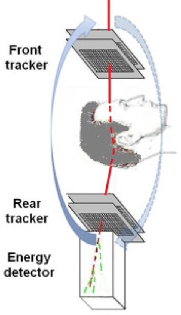
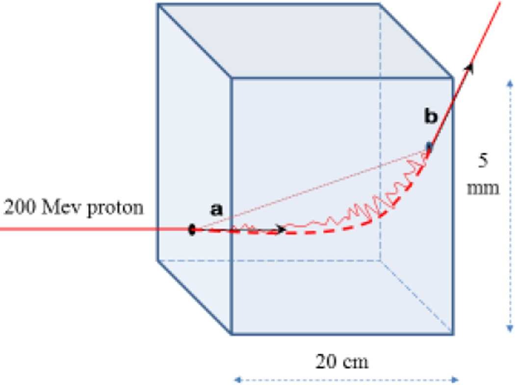
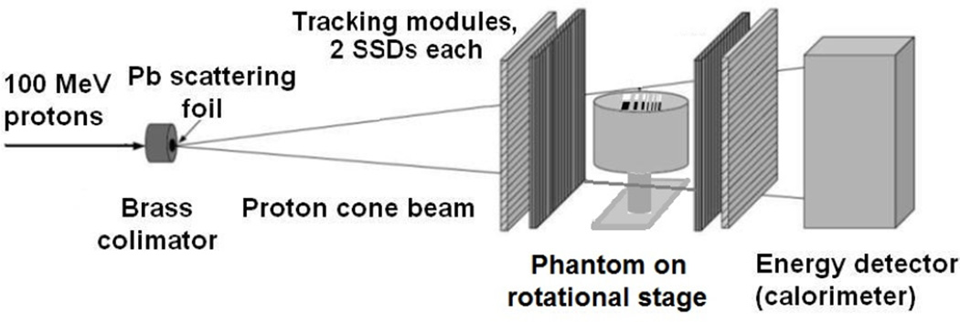
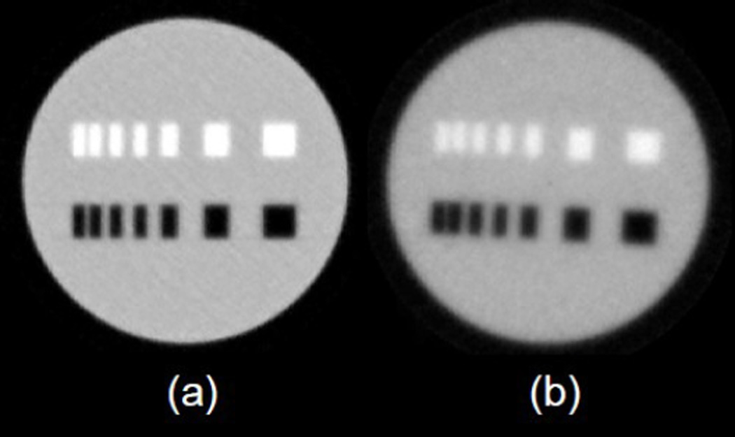
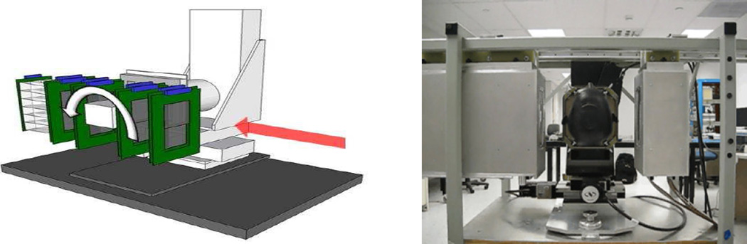
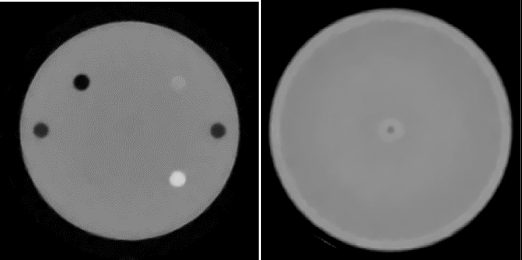
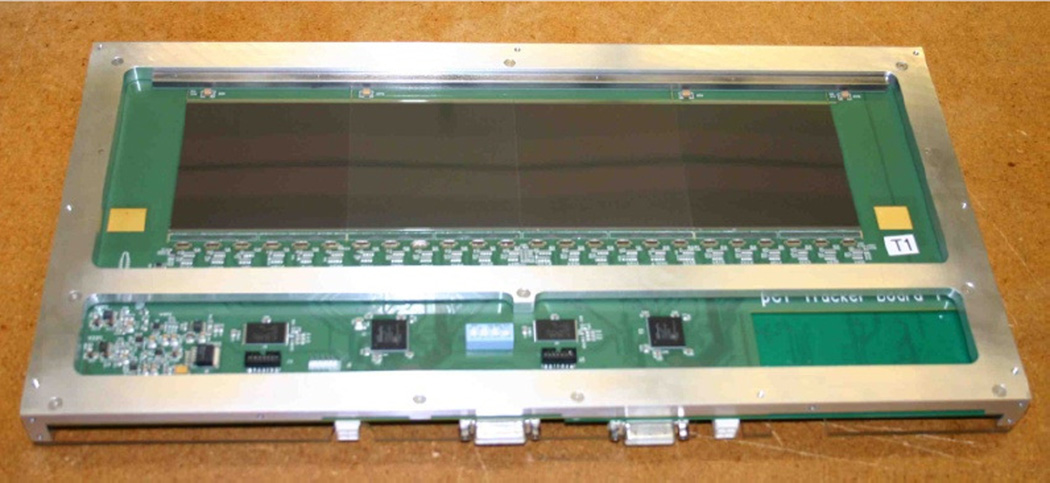
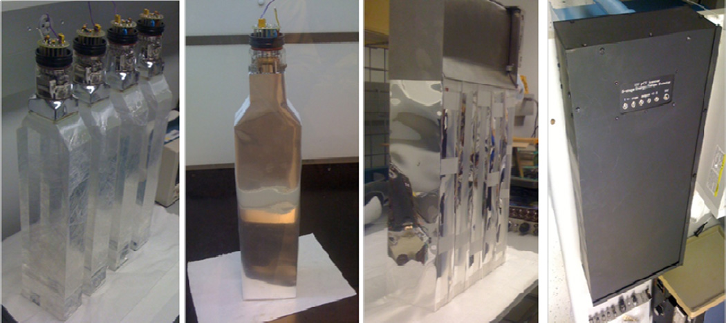
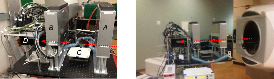
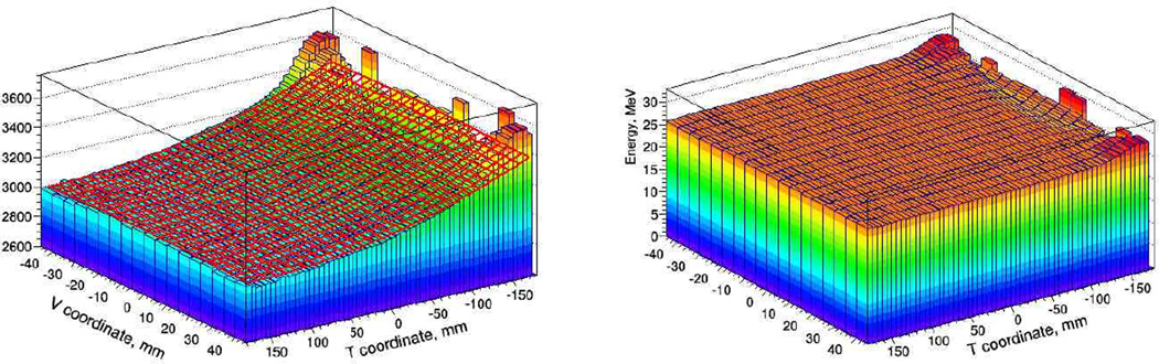
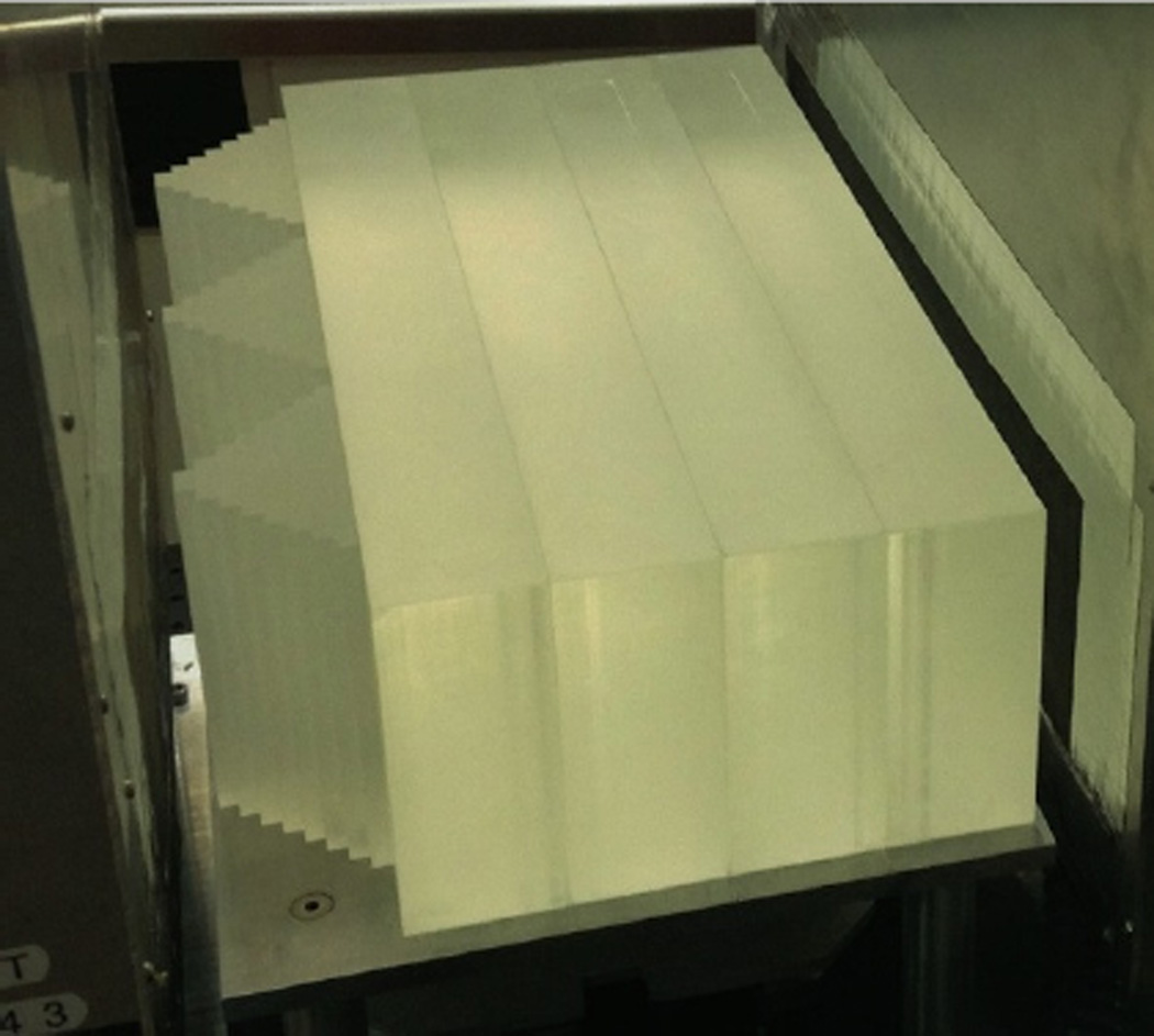
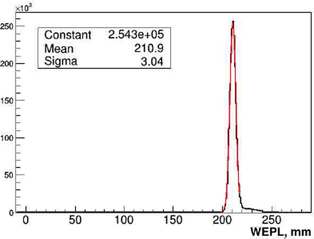
Radiation therapy with protons and heavier ions is an attractive form of cancer treatment that could enhance local control and survival of cancers that are currently difficult to cure and lead to less side effects due to sparing of normal tissues. However, particle therapy faces a significant technical challenge because one cannot accurately predict the particle range in the patient using data provided by existing imaging technologies. Proton computed tomography (pCT) is an emerging imaging modality capable of improving the accuracy of range prediction. In this paper, we describe the successive pCT scanners designed and built by our group with the goal to support particle therapy treatment planning and image guidance by reconstructing an accurate 3D map of the stopping power relative to water in patient tissues. The pCT scanners we have built to date consist of silicon telescopes, which track the proton before and after the object to be reconstructed, and an energy or range detector, which measures the residual energy and/or range of the protons used to evaluate the water equivalent path length (WEPL) of each proton in the object. An overview of a decade-long evolution of the conceptual design of pCT scanners and their calibration is given. Results of scanner performance tests are presented, which demonstrate that the latest pCT scanner approaches readiness for clinical applications in hadron therapy.

Keywords: WEPL; hadron therapy; head scanner; proton computed tomography; proton detector; range measurement.


Figures

Fig. 1
Fig. 1
The pCT scanner design concept based on individual proton tracking and energy measurement. The scanner rotates about the object together with a proton gantry delivering a broad beam of protons, which are tracked individually.
Fig. 2
Fig. 2
Illustration of the MLP concept (not to scale) The solid line represents the trajectory of a proton undergoing (exaggerated) multiple Coulomb scattering in a water slab. Vectors a and b (generally non-coplanar) represent proton entry and exit directions, respectively, necessary to evaluate the MLP. The dashed line shows the MLP and the dotted line corresponds to a straight-line approximation used in regular CT reconstruction.
Fig. 3
Fig. 3
Proton cone beam set-up used in a proof-of-principal experiment to test the pCT reconstruction based on the MLP concept.
Fig. 4
Fig. 4
Axial 2D phantom images reconstructed using ART and the MLP concept from (a) simulated and (b) experimental data.
Fig. 5
Fig. 5
Schematic drawing (left) and photo of the Phase I pCT scanner with head phantom installed on the rotational stage.
Fig. 6
Fig. 6
Left: reconstructed slice of the spherical Lucy phantom [19]. Bone, lucite and air inserts are visible (as well as pegs at the left and right sides of the phantom connecting phantom hemispheres). The polystyrene cylinder (lower left insert) is barely distinguishable because its stopping power is practicaly the same as that of polystyrene phantom body. Right image: reconstructed slice of the water phantom[17]; the central ring is an artifact caused by the incompletely corrected overlap of Si tracker planes planes.
Figure 7
Figure 7
Cassette with two PCBs installed. PCB accommodating 4 SSDs with vertical strip orientation is visible. 24 custom 64-channel frontend ICs [25] are positioned along the edge of the sensitive area to amplify and digitize the signals from the strips.
Figure 8
Figure 8
Assembly of the 5-stage detector
Figure 9
Figure 9
Left pane: The Phase-II pCT head scanner installed in the research beam line at Loma Linda proton synchrotron. The front tracker (A), rear tracker (B), the phantom rotation stage (C), and 5-stage detector (D) are labeled. The red arrow indicates the proton beam direction. Right pane: the same scanner installed on a robotic arm in gantry room at Northwestern Medicine Chicago Proton Center.
Fig. 10
Fig. 10
Left pane: parameterization of stage response with quadratic function of T and V coordinates. Right pane: stage response in energy units, corrected for track position.
Fig. 11
Fig. 11
Calibration set-up: polystyrene step phantom with four additional polystyrene bricks installed in-between tracking modules.
Figure. 12
Figure. 12
WEPL distribution for 1M 200 MeV protons traversing a 203.2 mm thick (211 mm water equivalent) polystyrene slab.
Figure 13
Figure 13
Axial 2D image of the CTP404 module reconstructed with data from the Phase II pCT scanner.
Figure 14
Figure 14
3D rendering of the pCT-reconstructed RSP map of a pediatric anthropomorphic head phantom.
Figure 15
Figure 15
Three cardinal planes of 3D RSP images obtained with Phase II scans of the anthropomorphic head phantom. There are some artifacts in these images, which are currently being addressed in the reconstruction method

References

    1. Hanson KM, et al. Phys. Med. Biol. 1981;26:965. - PubMed
    1. Cormack A. J. Appl. Phys. 1963;34:2722.
    1. Cormack AM, Koehler AM. Phys. Med. Biol. 1976;4:560. - PubMed
    1. Hanson KM. IEEE Trans. Nucl. Sci. 1979;26:1635–1640.
    1. Schulte R, et al. IEEE Trans. Nucl. Sci. 2004;51:866.