Review
. 2016 Mar-Apr;17(2):182-97.
doi: 10.3348/kjr.2016.17.2.182. Epub 2016 Mar 2.

Three-Dimensional Printing: Basic Principles and Applications in Medicine and Radiology

Affiliations
Review

Three-Dimensional Printing: Basic Principles and Applications in Medicine and Radiology

Guk Bae Kim et al. Korean J Radiol. 2016 Mar-Apr.

Abstract

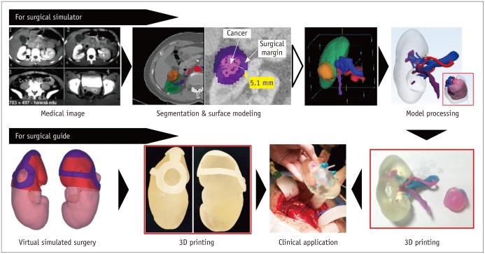
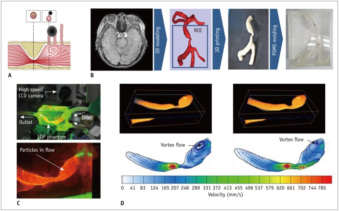
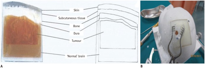
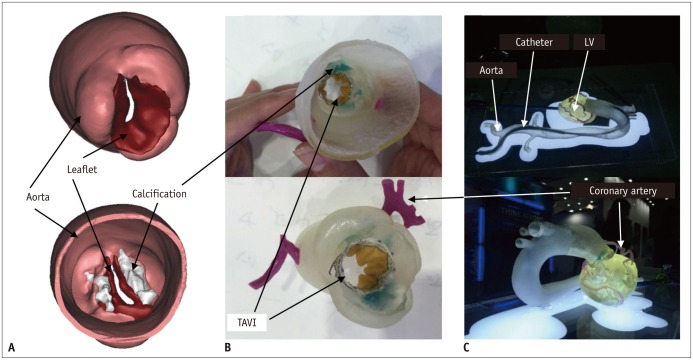
The advent of three-dimensional printing (3DP) technology has enabled the creation of a tangible and complex 3D object that goes beyond a simple 3D-shaded visualization on a flat monitor. Since the early 2000s, 3DP machines have been used only in hard tissue applications. Recently developed multi-materials for 3DP have been used extensively for a variety of medical applications, such as personalized surgical planning and guidance, customized implants, biomedical research, and preclinical education. In this review article, we discuss the 3D reconstruction process, touching on medical imaging, and various 3DP systems applicable to medicine. In addition, the 3DP medical applications using multi-materials are introduced, as well as our recent results.

Keywords: 3D printing; Biomedical research; Customized implant; Multi-materials; Personalized treatments; Preclinical education.


Figures

Fig. 1
Fig. 1. Overall procedure for 3D printing from medical images.
3D = three-dimensional
Fig. 2
Fig. 2. Basic principle of stereolithography apparatus method.
Fig. 3
Fig. 3. Basic principle of multi-jet printing method.
UV = ultraviolet
Fig. 4
Fig. 4. Basic principle of PolyJet method.
UV = ultraviolet
Fig. 5
Fig. 5. Basic principle of digital light processing method.
Fig. 6
Fig. 6. Basic principle of selective laser sintering method.
Fig. 7
Fig. 7. Basic principle of color-jet printing method.
Fig. 8
Fig. 8. Basic principle of fused deposition modeling method.
Fig. 9
Fig. 9. 3D-printed simulator for extended septal myectomy.
A. Cardiac three-chamber CT image showing hypertrophied interventricular septum (asterisks), posterior papillary muscle (P), and intraventricular muscle band or accessory papillary muscles (arrowhead). B. Bull's-eye map generated using end-diastolic phase of CT imaging shows extent of hypertrophied myocardium (red area, > 15 mm in thickness). C. 3D reconstructed model. D-F. 3D-printed phantom of myocardium showing geometric relationships among hypertrophied septum (asterisks), papillary muscle (A = anterior, P = posterior), and intraventricular muscle band (asterisks). G. Intraoperative photography via apical approach shows limited visual field of LV cavity. Base of anterior papillary muscle is exposed after excision of muscle band (not shown) near anterior papillary muscle. Adapted from Yang DH et al. Circulation 2015;132:300-301, with permission of Wolters Kluwer Health, Inc. (43). AO = aorta, LA = left atrium, LV = left ventricle, MV = mitral valve, 3D = three-dimensional
Fig. 10
Fig. 10. 3DP application in partial nephrectomy.
A. CT-image-based modeling of renal cell carcinoma and safety margin for carcinoma surgery. B. 3D-reconstructed model of all renal units with renal mass, which includes safety margin. C. 3D-printed phantom. Part of carcinoma including safety margin can be separated. D. Photograph of 3DP phantom in operating room. E-H. Another case of 3DP phantom used in surgery. 3DP phantom and real renal mass were compared after partial nephrectomy. 3DP = three-dimensional printing
Fig. 11
Fig. 11. 3D printing-mold-based personalized stent.
A. CT-based primary three-dimensional (3D) reconstruction. B. 3D-reconstructed model of main structural parts. C. 3D-printed phantom mold of main structural parts with Alumide material. D. Personalized stent with nitinol material. E. Equipped state of developed stent in introducer. F, G. Two different prototypes equipped with self-expanding bio-prosthetic valve. H-J. Results of animal study that involved implantation of developed stent. Post-mortem autopsy (H, I) and CT fluoroscopy (J) revealed accurate positioning of valve prostheses. Adapted from Amerini et al. Interact Cardiovasc Thorac Surg 2014;19:414-418, with permission of Oxford University Press (51).
Fig. 12
Fig. 12. Pilot study of patient-specific implant device with flexible material.
A. CT-based three-dimensional (3D) reconstruction of patient-specific dead zone after pneumonectomy. B. 3D-modeled dead zone and frame for molding. C. Fabricated negative mold with silicon material. D. Final product of spacer for dead zone with silicon material using molding technique.
Fig. 13
Fig. 13. 3DP-mold-based phantom for aortic dissection.
A. 3DP-based silicone phantom of aortic dissection. Adapted from Veeraswamy RK et al. J Vasc Surg 2015;61:128S-129S, with permission of Elsevier (64). B. Four-dimensional flow MRI image showing intimo-medial flap (arrow and arrowheads); flow is directed horizontally into true lumen at both entry and exit tears during diastole. Adapted from Birjiniuk J et al. J Surg Res 2015;198:502-507, with permission of Elsevier (63). C. Cross-sectional velocity fields at true and false lumina in representative axial plan. 3DP = three-dimensional printing
Fig. 14
Fig. 14. Fluid dynamic study of paramedian pontine infarction.
A. Schematic of mechanism for generating PPI. Adapted from Kim BJ et al. J Stroke Cerebrovasc Dic 2014;23:1991-1993 (65). B. Fabrication of transparent patient-specific BA phantom for optical flow measurement. C. Experimental setup of PIV measurement using manufactured BA phantom. D. Quantitative hemodynamic information of velocity field and vortex position in poststenotic area of BA. BA = basilar artery, PDMS = polydimethylsiloxane, PIV = particle image velocimetry, PPI = paramedian pontine infarction, 3DP = three-dimensional printing
Fig. 15
Fig. 15. Neurosurgical phantoms with pathological entity.
A. Cross-sectional view of 3DP phantom and drawing of parts thereof. B. Photograph showing burr hole with intact dura in training procedure. Adapted from Waran V et al. J Neurosurg 2014;120:489-492, with permission of JNSPG (69). 3DP = three-dimensional printing
Fig. 16
Fig. 16. 3DP phantom for training in transcatheter aortic heart valve implantation.
A. 3D reconstructed model based on real case. B. Multi-material 3DP phantom for TAVI. C. Simulation of catheterization for TAVI stent showing aortic valve 3DP phantom with TAVI stent inside. LV = left ventricular, TAVI = transcatheter aortic valve implantation, 3DP = three-dimensional printing

References

    1. Kido T, Kurata A, Higashino H, Sugawara Y, Okayama H, Higaki J, et al. Cardiac imaging using 256-detector row four-dimensional CT: preliminary clinical report. Radiat Med. 2007;25:38–44. - PubMed
    1. Meaney JF, Goyen M. Recent advances in contrast-enhanced magnetic resonance angiography. Eur Radiol. 2007;17(Suppl 2):B2–B6. - PubMed
    1. Doi K. Diagnostic imaging over the last 50 years: research and development in medical imaging science and technology. Phys Med Biol. 2006;51:R5–R27. - PubMed
    1. Kirchgeorg MA, Prokop M. Increasing spiral CT benefits with postprocessing applications. Eur J Radiol. 1998;28:39–54. - PubMed
    1. McGurk M, Amis AA, Potamianos P, Goodger NM. Rapid prototyping techniques for anatomical modelling in medicine. Ann R Coll Surg Engl. 1997;79:169–174. - PMC - PubMed

Publication types