. 2016 Mar 3;10(2):024103.
doi: 10.1063/1.4943124. eCollection 2016 Mar.

Rapid mask prototyping for microfluidics

Affiliations

Rapid mask prototyping for microfluidics

B G C Maisonneuve et al. Biomicrofluidics. .

Abstract

With the rise of microfluidics for the past decade, there has come an ever more pressing need for a low-cost and rapid prototyping technology, especially for research and education purposes. In this article, we report a rapid prototyping process of chromed masks for various microfluidic applications. The process takes place out of a clean room, uses a commercially available video-projector, and can be completed in less than half an hour. We quantify the ranges of fields of view and of resolutions accessible through this video-projection system and report the fabrication of critical microfluidic components (junctions, straight channels, and curved channels). To exemplify the process, three common devices are produced using this method: a droplet generation device, a gradient generation device, and a neuro-engineering oriented device. The neuro-engineering oriented device is a compartmentalized microfluidic chip, and therefore, required the production and the precise alignment of two different masks.


Figures

FIG. 1.
FIG. 1.
Overview of the rapid fabrication process.
FIG. 2.
FIG. 2.
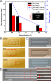
(a) FOE and size of the individual pixel for different objectives. (b) Pictures of the masks used to test the videoprojector capabilities. (c) Pictures of the some features (3 × 5 pixels) obtained with the different magnification. (d) Picture of the smallest features obtained (2 × 2 pixels) with the ×2.5.
FIG. 3.
FIG. 3.
Design of the two layers of the microfluidic device. (a) Picture of the mask used for the bottom layer, (b) picture of the mask used for the top layer, (c) SEM images of the mask, the SU8 master, and the resulting PDMS device. The proposed technology allows clean and precise fabrication of microfluidic geometries.
FIG. 4.
FIG. 4.
Drop generation device. (a) Design of the mask, (b) picture of a microfluidic device, filled with some rhodamine-B, (c) image of the generation of droplets (water in oil).
FIG. 5.
FIG. 5.
Concentration gradient generation device. (a) Picture of a microfluidic device, filled with some Rhodamine-B, (b) design of the mask, (c) image of the concentration gradient generated (fluorescein and water).
FIG. 6.
FIG. 6.
Compartmentalized neurons culture device. (a) Design of the mask of the bottom layer of the device. (b) Picture of a microfluidic device, filled with some Rhodamine-B in the cell body chamber (right on the image) and some fluorescein in the axon chamber (left on the image). (c) Picture of the device, with some neurons in culture in the (10DIV) in the right chamber, and with some axons crossing all the way to the left chamber.

References

    1. Xia Y. and Whitesides G. M., Annu. Rev. Mater. Sci. 28, 153 (1998).10.1146/annurev.matsci.28.1.153 - DOI
    1. Zhao S., Cong H., and Pan T., Lab Chip 9, 1128 (2009).10.1039/b817925e - DOI - PubMed
    1. Wang T., Quaglio M., Pirri F., Cheng Y.-C., Busacker D., and Cerrina F., Proc. SPIE 7274, 727420 (2009).10.1117/12.814831 - DOI
    1. Chung S. E., Park W., Park H., Yu K., Park N., and Kwon S., Appl. Phys. Lett. 91, 41106 (2007).10.1063/1.2759988 - DOI
    1. Dreyfus R., Tabeling P., and Willaime H., Phys. Rev. Lett. 90, 144505 (2003).10.1103/PhysRevLett.90.144505 - DOI - PubMed